background image


Introduction


Page 1-2


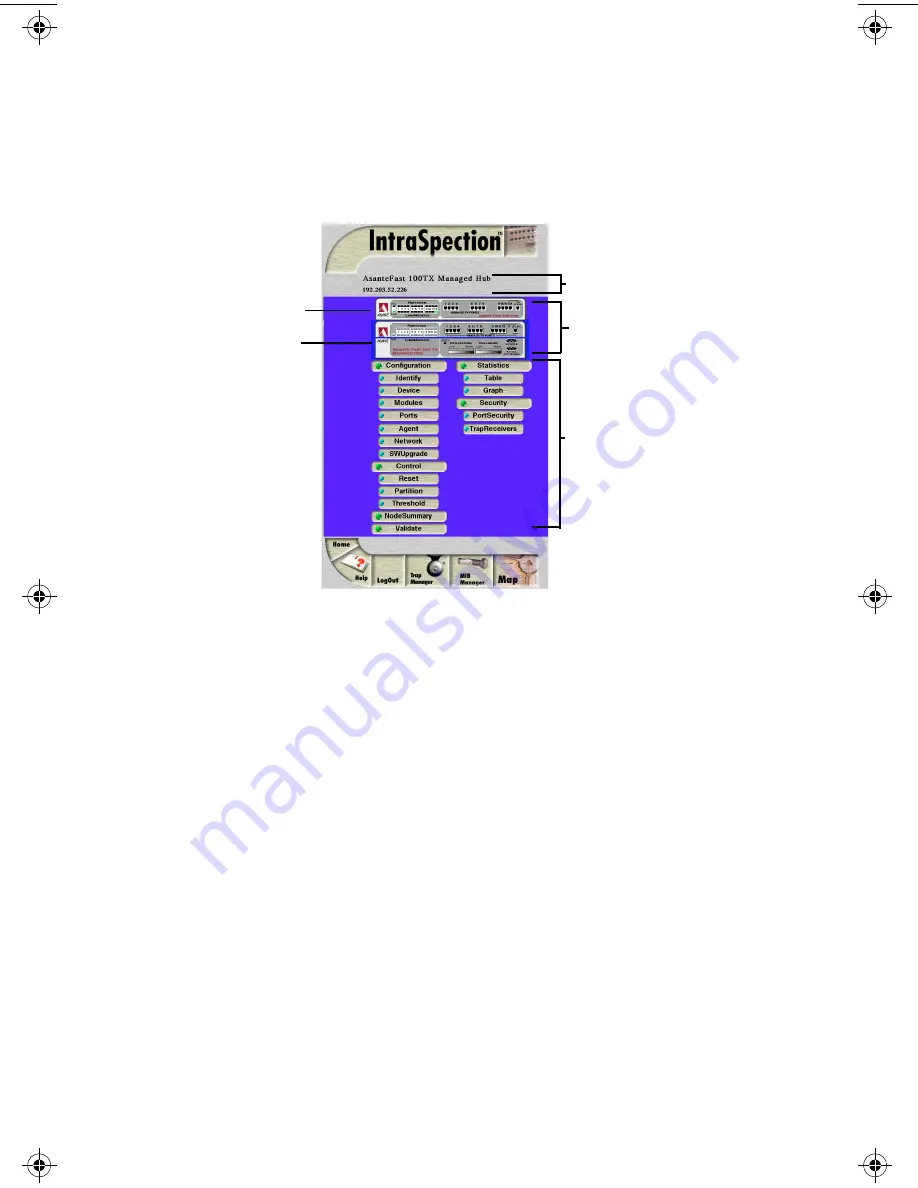
AsantéFAST 100 TX Managed Hub Personality Module


The AsantéFAST 100 TX Managed Hub Personality Module allows for 
expanded management of an AsantéFAST 100TX Managed Hub or a 
stack of 100 Hubs with an attached Managed Hub.  See Figure 1-2.


Figure 1-2

AsantéFAST 100 TX Managed Hub Device Page


Management Options


Both the AsantéFAST 100 Hub and the AsantéFAST 100 TX Managed Hub 
Personality Modules support the following management options:

See Chapter 4 “Menus” for a complete description of each management 
option.

AsantéFAST 100 Hub

AsantéFAST 100 TX 

Device Information

Front Panel Image

Personality Module
Information
 (menus)

Managed Hub

Device identification

General device infor-
mation

Module information

Port information

SNMP agent 
information

Network access 
configuration

Software upgrades 

Device and group resets

Group and port partition-
ing

Alarm thresholds

Node summary informa-
tion

Table statistics at the 
device/group/port levels

Graph statistics at the 
device/group/port levels

Port security

Trap receiver management


100NMM PM book  Page 2  Wednesday, August 27, 1997  12:40 PM

Summary of Contents for AsanteFAST 100

Page 1: ...on Personality Modules AsantéFAST 100 Hub AsantéFAST 100 TX Managed Hub User s Manual Asanté Technologies Inc 821 Fox Lane San Jose CA 95131 1 800 662 9686 www asante com August 1997 Part Number 06 00341 00 Rev A ...

Page 2: ... REMEDIES AsantéTechnologies and its suppliers entire liability and your exclusive remedy shall be at AsantéTechnologies option either a return of the price paid or b repair or replacement of the SOFTWARE that does not meetAsantéTechnologies LimitedWarranty and which is returned toAsantéTechnologies with a copy of your receipt This Limited Warranty is void if failure of the SOFTWARE has resulted f...

Page 3: ...nstallation 2 1 Installing a Personality Module 2 1 Management 3 1 Accessing the Device Page 3 1 Device Page Components 3 3 Front Panel Image Components 3 4 Selecting the Device for Management 3 5 Menu Components 3 6 Tables 3 6 Table Columns 3 6 Buttons 3 6 Performing Basic Management Functions 3 7 Setting Community Strings 3 8 Configuring Network Access Parameters 3 10 Configuring Device Identifi...

Page 4: ...ng Trap Receivers 3 22 Setting Alarms 3 24 Viewing Node Summary Information 3 27 Setting Port Security 3 28 Viewing Statistics 3 30 Menus 4 1 Configuration 4 3 Identify 4 3 Device 4 4 Modules 4 5 Ports 4 6 Agent 4 8 Network 4 9 SWUpgrade 4 10 Control 4 11 Reset 4 11 Partition 4 12 Threshold 4 13 Node Summary 4 16 Validate 4 17 Statistics 4 17 Table 4 17 Graph 4 19 Security 4 20 Port Security 4 20 ...

Page 5: ...gure 1 2 This manual provides information for two Personality Modules The AsantéFAST 100 Hub Personality Module The AsantéFAST 100TX Managed Hub Personality Module AsantéFAST 100 Hub Personality Module The AsantéFAST 100 Hub Personality Module allows for expanded man agement of an AsantéFAST 100 Hub or stack of 100 Hubs with an attached AsantéFAST 100 Management Module See Figure 1 1 Figure 1 1 As...

Page 6: ... the following management options See Chapter 4 Menus for a complete description of each management option AsantéFAST 100 Hub AsantéFAST 100 TX Device Information Front Panel Image Personality Module Information menus Managed Hub Device identification General device infor mation Module information Port information SNMP agent information Network access configuration Software upgrades Device and gro...

Page 7: ...management system that supports ODBC such as Microsoft Access Oracle or Microsoft SQL Server Client Any Windows Windows NT Macintosh or UNIX workstation Any World Wide Web browser with Java and Java Script support such as Netscape Navigator version 3 0 required 3 01 recommended or Microsoft Inter net Explorer Installation TheAsantéFAST 100 Hub andAsantéFAST 100TX Managed Hub are two separate Perso...

Page 8: ...ersonality Modules Chapter 2 Installation explains how to install the AsantéFAST 100 and AsantéFAST 100TX Managed Hub Personality Modules Chapter 3 Management explains how to access and use a Personality Module s Device Page and how to perform some basic management func tions Chapter 4 Menus describes each management menu and its contents ...

Page 9: ... exe is NOT running on the computer 1 Insert the Personality Module CD into the computer where the IntraSpection Application Server is installed 2 Open the CD to display its contents 3 Double click the 100NMM exe file 4 Click Yes at the IntraSpection Personality Module Installation Confirmation dialog box The IntraSpection Personality Module information window appears 5 Click Finish to continue Th...

Page 10: ...ource is Now Complete dialog box appears 9 Click OK to continue with the installation The Select Module to Install window appears dis playing the 100NMM ipm file See Figure 2 1 Figure 2 1 Select Module to Install window 10 Click once on the 100NMM ipm file 11 Click Open The Enter Product Serial Number window appears 12 Enter the serial number that came with your copy of the Personality Module The ...

Page 11: ...ow may appear if it does click OK The installer program installs both Personality Mod ules into the IntraSpection Application Server Installation is complete when the Installation Com pleted Successfully dialog box appears 15 Start the IntraSpection Application Server following the guidelines below Windows NT 3 51 users double click the IntraSpection icon located in the Programs group Windows NT 4...

Page 12: ......

Page 13: ...ires logging into IntraSpection Important For help on accessing and logging into IntraSpection refer to the IntraSpection User s Manual 3 After you are logged into IntraSpection click Auto Discovery on the IntraSpection Main Menu The AutoDiscovery Page appears 4 Complete each field on the AutoDiscovery Page fol lowing the guidelines below Type the IP subnet address of the AsantéFAST 100 Hub stack ...

Page 14: ...uffer if any 5 Click Apply IntraSpection builds a map of your network The map con tains icons which represent each discovered SNMP device on the network Figure 3 1 is an example map Figure 3 1 Discovered network map 6 Click once on the AsantéFAST 100 Hub or AsantéFAST 100TX Managed Hub s icon The Device Page for the selected hub appears see Figure Figure 3 2 on page 3 3 For information on the Devi...

Page 15: ...100TX Managed Hub Personality Modules are the same except for the device information and the front panel image See Figure 3 3 Figure 3 3 AsantéFAST 100 Hub and AsantéFAST 100TX Managed Hub Device Pages Device Information device description and IP address Front Panel Image entire hub stack collectively referred to as a single device each module referred to as a group Personality Module Information ...

Page 16: ...tack of hubs the term group refers to an individual module the term port refers to an individual port Group Numbering For management purposes each group within a device is assigned a number The bottom module is always group 15 the next module up is group 14 etc Important The AsantéFAST 100TX Managed Hub mod ule contains two groups the management module and the hub therefore it uses two group numbe...

Page 17: ...e Reset menu that group module will be reset If the device is selected and you select Reset the device entire hub stack will be reset Selecting an Item Deselecting an Item Target Item Action Device entire hub stack Do not click anything on the front panel image Group single module Click once on the group Port Click once on the port Target Item Action Device Click once on a group or port Group Clic...

Page 18: ...nformation Read only Information Table Columns Table columns can be resized by placing the mouse pointer on a column title s left or right side until a double arrow appears and dragging the column to the left or to the right as desired Buttons Some menus contain buttons which allow you to edit and or update the page Menu item Action Drop down menu Select from an available option White colored fiel...

Page 19: ...e 3 10 Configuring device identification information page 3 11 Management Task Page Updating the Device Page page 3 13 Viewing general device information page 3 14 Viewing module information page 3 15 Viewing SNMP agent Information page 3 16 Enabling disabling ports page 3 17 Disabling a group page 3 18 Partitioning a port page 3 19 Resetting a group or device page 3 20 Enabling traps page 3 21 Ma...

Page 20: ...le Important It is recommended that you set the commu nity strings for an AsantéFAST 100 Hub stack in IntraSpec tion before you attempt to perform any network management functions This section describes how to set the community strings in IntraSpec tion to match those set in the management module To set the community strings for a management module in IntraSpec tion 1 On the Device Page click the ...

Page 21: ...to Figure 3 8 Figure 3 8 Map ConfigurationTable 4 Enter the management module s IP address in the IP Address field 5 Enter the management module s read community string in the Read field 6 Enter the management module s write community string in the Write field 7 Click Apply The read and write community strings for the manage ment module are configured ...

Page 22: ...is selects the entire hub stack 2 Click Network The Network Information table appears similar to Figure 3 9 Figure 3 9 Network Information table 3 Click once in the field to be edited For a description of each field see Network on page 4 9 Important If you change the IP address sub net mask and or default gateway you must reset the stack s management module See Reset ting a Group or Device on page...

Page 23: ...anel image This selects the entire hub stack 2 Click Identify The Device Identification table appears similar to Figure 3 10 Figure 3 10 Device Identification table 3 Click once in the field to be edited For a description of each field see Identify on page 4 3 Important Only those fields that are colored white or that contain drop down menus can be edited 4 Type the new information Important A max...

Page 24: ...ade table appears similar to Figure 3 11 Figure 3 11 Software Upgrade table 2 Type the software s file name and network path in the Boot File Name field 3 Type the server s IP address where the software file resides in the Server Address field 4 Click Apply 5 Reset the hub stack to initiate the downloading of the software See Resetting a Group or Device on page 3 20 Click Refresh to view updated i...

Page 25: ...u are viewing the hub s latest information To update the Personalty Module s Device Page 1 Click Validate The Device Page is updated with the latest information for the Personalty Module After the Device Page is updated the IntraSpection Map Manager Page appears 2 Click AutoDiscovery to rediscover the network map containing the devices Important See Accessing the Device Page on page 3 1 for instru...

Page 26: ...n number To view general device information 1 Do not select any item on the Device Page s front panel image This selects the entire hub stack 2 Click Device The Device Information table appears similar to Figure 3 12 Figure 3 12 Device Information table Note The information displayed on this page is read only For a description of each field see Device on page 4 4 3 Click Refresh to view updated in...

Page 27: ...nformation 1 Do not select any item on the Device Page s front panel image This selects the entire hub stack 2 Click Modules The ModuleTable appears similar to Figure 3 13 Figure 3 13 ModulesTable Note The information displayed on this page is read only For a description of each field see Modules on page 4 5 3 Click Refresh to view updated information ...

Page 28: ...entication status To view SNMP agent information 1 Do not select any item on the Device Page s front panel image This selects the entire hub stack 2 Click Agent The Agent Information table appears similar to Figure 3 14 Figure 3 14 Agent Information table For a description of each field see Agent on page 4 8 3 Click Refresh to view updated information Note For information on using theTrap Authen t...

Page 29: ...appears similar to Figure 3 15 Figure 3 15 PortTable The PortTable displays the current status of each port on each group within the device The table contains a scroll bar that is independent of the browser which allows you to view information on all ports in the device 2 Select the port to be enabled or disabled by clicking once on the port s row 3 Click Modify The Modify Dialog box appears 4 Ope...

Page 30: ...up numbering see Group Numbering on page 3 4 1 Select the group to be disabled on the Device Page s front panel image by clicking on it once 2 Click Partition The Board Partition table appears for the selected group similar to Figure 3 16 Figure 3 16 Board Partition table 3 Open the Action drop down menu and select disable 4 Click Apply The group is disabled Click Refresh to view updated informati...

Page 31: ...le automatic partitioning 1 Select the port to be partitioned or group containing the port by clicking on it once 2 Click Partition The Port Partition table appears similar to Figure 3 17 Figure 3 17 Port Partition table 3 Open the Action drop down menu and select enable to enable automatic partitioning or disable to dis able automatic partitioning 4 Click Apply The port s partitioning state is mo...

Page 32: ...anagement module To perform a reset 1 To reset a group click once on that group To reset the device do NOT select anything 2 Click Reset Depending on what was selected either a group or the device the Reset Group or Reset Agent table appears similar to Figure 3 18 and Figure 3 19 Figure 3 18 Group Reset table Figure 3 19 Device Reset table 3 Open the Action drop down menu and select reset 4 Click ...

Page 33: ...e This selects the entire hub stack 2 Click Agent The Agent Information table appears similar to Figure 3 20 Figure 3 20 Agent Information table 3 Open the Trap Authentication drop down menu and select enabled 4 Click Apply The management module is configured to generate traps Note For information on determining when a trap occurs see Setting Alarms on page 3 24 and Set ting Port Security on page ...

Page 34: ...rap Receiver TheTrap ReceiverTable appears similar to Figure 3 21 Figure 3 21 Trap ReceiverTable 3 Click Add The Add Dialog box appears 4 Open the Status drop down menu and select valid 5 Type the IP address of the management station that is to receive traps in the Trap Receiver Address field Important Do NOT type an IP address of 0 0 0 0 6 Type the community string for the management station in t...

Page 35: ...p down menu and select invalid 4 Click Apply 5 Click Refresh in theTrap ReceiverTable The trap receiver is deleted Modifying a Trap Receiver Entry To change the IP address of a trap receiver entry 1 Delete the trap receiver entry following the directions above 2 Add a new trap receiver entry following the instruc tions on page 3 22 The trap receiver entry s IP address is changed Click Refresh to v...

Page 36: ...larm 1 Do not select any item on the Device Page s front panel image This selects the entire device 2 Click Threshold The AlarmThresholdTable appears similar to Figure 3 22 Figure 3 22 AlarmThresholdTable Note If there are no alarm thresholds set the table is empty 3 Click Add to add an entry The Add Dialog box appears similar to Figure 3 23 Figure 3 23 Add AlarmThreshold Dialog box 4 Complete eac...

Page 37: ...a counter from the drop down menu See Subject on page 4 14 for a description of each counter Sample Type The unit of measure for the alarm This field cannot be edited it is always set to event persecond Startup Event Determines when the alarm is to be triggered Select rising falling or ris ingANDfalling from the drop down menu See Startup Event on page 4 15 for a descrip tion of each event Thresho...

Page 38: ...larm entry to be modified by clicking once on its row in the AlarmThresholdTable 2 Click Modify The Modify Dialog box appears 3 Modify the parameters as desired following the guide lines on page 3 25 4 Click Apply The alarm is modified Click Refresh to view updated information Field Description Action Sampling Interval The polling interval that determines how often to make the measurement Enter a ...

Page 39: ...ular group click once on a group 2 Click Node Summary The Node Summary table appears for the device or selected group similar to Figure 3 24 Figure 3 24 Node SummaryTable You can set the amount of time each entry remains in the table by typing the number of seconds in the NodeAging Timer field and clicking Apply The default setting is 1 this value prevents the table from updating the value 4 294 9...

Page 40: ...oning of the port sending of a trap etc can be specified to occur To set port security 1 Do not select any item on the Device Page s front panel image This selects the entire hub stack 2 Click Port Security The Port SecurityTable appears similar to Figure 3 25 Figure 3 25 Port SecurityTable 3 Click the Add button The Add Dialog box appears similar to Figure 3 26 Figure 3 26 Add Port Security Dialo...

Page 41: ...er in the Allowed Address field Important Enter the physical address in hexa decimal notation separated by colons For exam ple 00 00 94 C5 15 F1 8 Open the Violation Action drop down menu and select the violation action to occur if an unauthorized MAC address attempts to access the port For a description of each violation action see Violation Action on page 4 20 9 Click Apply The port security inf...

Page 42: ...cs appear for the group port or device selected similar to Figure 3 27 Figure 3 27 Table Statistics For a description of each object see Statistics on page 4 17 3 Open the Sampling Interval drop down menu and select the number of seconds to poll for statistics Statistics are automatically gathered in the following col umns Curr current the number of occurrences each second Peak the largest number ...

Page 43: ... to be monitored For a description of each object see Statistics on page 4 17 4 Open the Seconds drop down menu and select the number of seconds for which statistics are to be gath ered 5 Use the scroll button to change the graph s count per second display scroll up to increase the count per sec ond scroll down to decrease it Average per Second the average number of occurrences since opening or re...

Page 44: ......

Page 45: ...tion See Identify on page 4 3 Device Allows you to view general device information See Device on page 4 4 Modules Allows you to view information on the device s group types See Modules on page 4 5 Ports Allows you to view information for each port and enable and disable ports See Ports on page 4 6 Agent Allows you to view information on the device s SNMP agent such as software and firmware informa...

Page 46: ...Spection Application Server database See Vali date on page 4 17 Statistics Title for the submenus listed below it this menu cannot be selected See Statistics on page 4 17 Table Allows you to view real time statistical data in table format on the device See Table on page 4 17 Graph Allows you to view real time statistical data in graph for mat on the device See Graph on page 4 19 Security Title for...

Page 47: ... field displays the device s SNMP identify ing number Description Read only field displays a description of the device Name Configurable field assigns a name to the device Note A maximum of 254 characters including spaces is allowed Location Configurable field assigns a location to the device where the device is physically located Note A maximum of 254 characters including spaces is allowed Contac...

Page 48: ...ys the current version number of the device Revision Number Read only field displays the current revision number of the device Number of Groups Read only field displays the number of groups the device contains Chassis Type Read only field displays the device s chassis type Note This field always displays FastHub100 Backplane Type Read only field displays the device s backplane type Note This field...

Page 49: ...Note The table displays entries for groups 1 through 15 a module type of empty means that there is physi cally no group in that position in the device See Group Numbering on page 3 3 for more informa tion on groups and group numbering Description Read only field displays a description of the group HW Revision Number Read only field displays the hardware revision num ber of the device State Read on...

Page 50: ...r on the port for example RJ 45 Link Status Read only field displays if a device is connected to the selected port linkon a device is properly connected to the selected port and is powered on linkoff a device is not connected to the port AutoPort Status Configurable field displays the automatic partitioning status of the selected port autopartitioned the port is configured for automatic partitioni...

Page 51: ... Admin Status Configurable field determines the state of the port enabled the port is enabled and can receive packets disabled the port is disabled and cannot receive packets See Enabling Disabling Ports on page 3 17 for instructions ...

Page 52: ...rsion number of the device s management module Note If the unit is running code version 1 2 the FWVersion Major number is 1 FWVersion Minor Read only field displays the minor firmware version number of the device s management module Note If the unit is running code version 1 2 the FWVersion Major number is 2 Trap Authentication Configurable field indicates if the device can send traps to the trap ...

Page 53: ...onfigurable field displays the IP address of the man agement module s SNMP agent Subnet Mask Configurable field displays the subnet address of the device Note A subnet mask in the IP addressing scheme is a group of selected bits whose values serve to identify a subnetwork All members of the subnetwork share the mask value Default Gateway Configurable field displays the address of the default gatew...

Page 54: ... number is 2 Boot File Name Configurable field sets the network path and name of the boot file for the device Server Address Configurable field sets the boot server s IP address Image Load Mode Configurable field determines the method for loading the software localBoot sets the device to boot from code stored in device default setting netBoot sets the device to boot from a TFTP server on the netwo...

Page 55: ...ote For instructions on using this menu see Resetting a Group or Device on page 3 20 Table 4 9 Reset Menu Field Description Device Level Reset Agent Reset Agent Configurable field resets the device reset resets the device not reset does not reset the device Group Level Reset Group Group Number Read only field displays the number of the group to be reset Action Configurable field resets the group r...

Page 56: ...19 Table 4 10 Partition Menu Field Description Group Level Board Partition Group Number Read only field displays the number of the selected group to be disabled Action Configurable field disables or enables the group disable disables the selected group enable enables the selected group Port Level Group Number Read only field displays the number of the group to which the selected port belongs Port ...

Page 57: ...figurable field displays the status of the entry in the table valid active entry invalid inactive entry deletes the entry when selected Target Domain Configurable field determines the portion of the device for which alarms are being set port sets the alarm for a specific port you must enter the port number in the Target Port field group sets the alarm for a specific group you must enter the group ...

Page 58: ... Check CRC dataratemismatch the number of errors where the incoming data rate is not within the tolerance level of 10Mhz or 0 01 shortevents the number of data bursts where data is less than 10 bytes in length collisions the total number of collisions latecollisions the number of collisions that occurred after the 64 byte collision window autopartitions the number of times the port was automatical...

Page 59: ... trap to the receiving trap station partitionportANDsendtrap partitions the target port and sends a trap sendtrapANDrequestpage sends a trap and sends a page to the network administrator if the trap receiving station is an AsantéView Management Station partitionportANDsendtrapANDrequestpage partitions the target port sends a trap and send a page to the network administrator if the trap receiving s...

Page 60: ...mber including 1 prevents the table from updating When this value is entered in the Node Aging Timer field the value 4 294 967 295 is displayed 0 entries are not deleted from the table The amount of time is rounded to the nearest minute Group Number Read only field displays the number of the selected group Port Number Read only field displays the number of the port on the group Last IP Address Rea...

Page 61: ... see View ing Statistics on page 3 30 Table 4 13 Table Menu Field Description Sampling Interval Configurable field allows you to set the amount of time in seconds that the device group port is polled for information Reset Button resets the counters to zero in the statistics table Objects Good Frames the total number of good or readable frames frames without error FramesTooLongErrors the number of ...

Page 62: ...data is less than 10 bytes in length MauJabberLockups the number of times the hub repeater chip goes into a lockup state Auto Partitions the number of times the port was automatically partitioned in response to 31 or more continuous collisions Bad Frames the number of invalid frames including toolong runts misaligned or bad FCS Readable Octets the total number of octets received from valid frames ...

Page 63: ...h statistics are gathered Note For a description of each object see Objects on page 4 17 Average per sec ond Displays the average number of occurrences since opening or resetting the screen Reset Statistics Button resets the counters to zero in the graph Peak per second Displays the largest number of occurrences since opening or resetting the screen Count per second display Displays the amount of ...

Page 64: ...roup selected Port Index Read only field displays the number of the port on the group Status Configurable field determines the status of the entry valid entry is active invalid entry is inactive deletes the entry Allowed Address Configurable field displays the physical address that is allowed to connect to the specified port Violation Action Configurable field the action to occur if the physical a...

Page 65: ...ription Status Configurable field displays the status of the trap receiving station s entry valid trap receiver entry is active invalid trap receiver entry is inactive deletes the trap receiver s entry in the table when selected Trap Receiver Address Configurable field displays the IP address of the man agement station that can receive traps To change or add an address see Managing Trap Receivers ...

Page 66: ......

Page 67: ... 408 432 6018 Fax Back 800 741 8607 408 954 8607 Internet Mail support asante com World Wide Web http www asante com Bulletin Board Service BBS 408 432 1416 ARA BBS guest log in 408 894 0765 AppleLink mail BBS ASANTE FTP Archive ftp asante com Technical Support Hours 6 00 A M to 5 00 P M Pacific StandardTime USA Monday Friday ...

Page 68: ......

Page 69: ...ule overview 1 2 assistance See technical support auto partitions 4 18 AutoDiscovery See network map automatic partitioning configuring 3 19 description 4 6 B backplane revision description 4 4 type description 4 4 bad frames 4 18 baud rate configuring 3 10 description 4 9 boot file name 4 10 configuring 3 12 server address configuring 3 10 3 12 description 4 9 4 10 booting from the network 4 10 l...

Page 70: ...8 minor 4 8 frames bad 4 18 too long errors 4 17 front panel image 3 4 See also device G gateway default configuring 3 10 description 4 9 good frames 4 17 graph menu 4 19 statistics 3 31 graphic of device See front panel image groups defined 3 4 enabling disabling 3 18 number of 4 4 numbering 3 4 reset description 4 11 resetting 3 20 viewing image of 3 4 H hardware revision number 4 5 help See tec...

Page 71: ...nents 3 3 updating 3 13 general device information viewing 3 14 management continued graph menu 4 19 statistics 4 19 groups enabling disabling 3 18 identify menu 4 3 menus components of 3 6 configurable information determining 3 6 overview 4 1 read only information determining 3 6 modules menu 4 5 viewing 3 15 network access parameters configuring 3 10 menu 4 9 node summary menu 4 16 partition men...

Page 72: ...ver 1 3 Navigator 1 3 network access parameters configuring 3 10 boot 4 10 map creating 3 1 menu 4 9 network continued problems isolating 3 19 node summary aging timer description 4 16 menu 4 16 timer configuring 3 27 viewing 3 27 number of addresses 4 16 O object ID 4 3 objects statistics description 4 17 ODBC 1 3 Oracle 1 3 out of band parameters configuring 3 10 overview personality modules 1 1...

Page 73: ...e window 2 2 selecting ports hubs hub stack 3 5 serial number location of 2 2 server requirements 1 3 server boot address configuring 3 12 server boot address continued description 4 10 short events 4 18 SNMP agent information viewing 3 16 community string See community strings software upgrade menu 4 10 information 4 10 upgrading 3 12 version major 4 8 4 10 minor 4 8 4 10 statistics graph 4 19 vi...

Page 74: ...eting 3 23 community string 4 21 menu 4 21 traps adding receiving stations 3 22 deleting receiving stations 3 23 enabling 3 21 U unauthorized community string description 4 8 IP address description 4 8 up time 4 3 4 4 updating hub or stack of hubs 4 17 V validate device 3 13 menu 4 17 version number 4 4 W websuite exe 2 1 Windows NT 3 51 requirements 1 3 starting IntraSpection server 2 2 Windows N...

Reviews: