


Aruba 387 Series Outdoor Access Points
| Installation Guide
7
Connecting the Ethernet Cable
To connect the Ethernet cable to the access point, perform the following steps using the Ethernet cable glands
that ships with your access point.
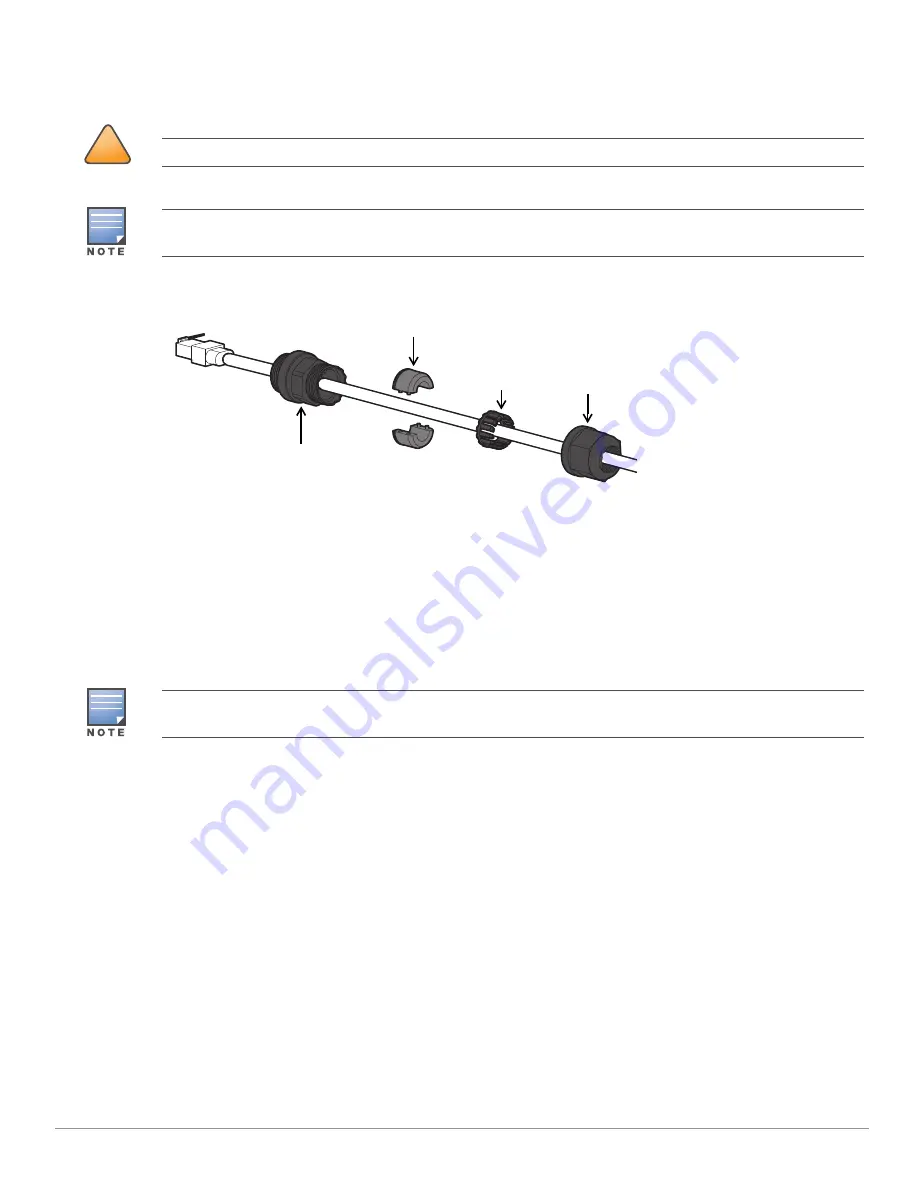
Figure 5
Installing the Ethernet Cable Gland
1. Remove the dust cap from the Ethernet port
2. Slide the sealing nut, clip, split grommet and gland body over the cable.
3. Insert the RJ45 connector to the Ethernet port.
4. Screw the gland body onto the Ethernet port.
5. Combine the two split parts of the grommet over the cable, and move it towards the gland body until it
locates at the recess of the gland body.
6. Move the clip towards the gland body, passing over the grommet, until the wavy end of the clip properly fits
into the wavy end of the gland body.
7. Screw the sealing nut onto the gland body.
Verifying Post-Installation Connectivity
The integrated LEDs on the access point can be used to verify that the access point is receiving power and
initializing successfully (see
). For instructions on initial setup and software configuration,
refer to the AP Software Quick Start Guide.
Electrical and Environmental Specifications
Electrical
Ethernet
One 100/1000Base-T auto-sensing Ethernet RJ-45 Interfaces
Power over Ethernet (IEEE 802.3at compliant)
Environmental
Operating
Temperature: -40ºC to 60ºC (-40ºF to 140ºF)
!
CAUTION
Failure to use the included Ethernet cable glands can lead to connectivity and POE issues.
The cable is not included and must be purchased separately. Purchase a suitable UV-resistant, outdoor rated,
CAT 5E or better RJ45 cable for use with the access point.
Sealing Nut
Clip
Gland Body
Split Grommet
Two grommets are provided in the package for use with the Ethernet cables. One is applicable for cables with
4-6 mm diameter, and another is applicable for cables with 6-10 mm diameter.


