


GRINDER MIXER ADJUSTMENTS
25
GRINDER MIXER ADJUSTMENTS
CAUTION: DO NOT MAKE ANY
ADJUSTMENTS WHILE THE MACHINE
IS
IN
OPERATION
AUGER/SUPPLEMENT.
D
RIVE
C
HAIN
A
DJUSTMENTS
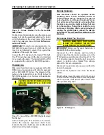
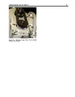
The mill to mixer auger/supplement hopper drive
chain and the discharge auger drive chain are
tensioned with an idler sprocket (See Figure 34).
Adjust the chain tension to 1/2 inch total deflection
by positioning the idler sprocket.
Figure 34 - Mill to Mixer Auger Drive Chain.
M
AIN
D
RIVE
C
HAIN
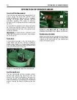
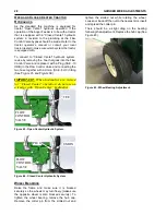
Adjust the tension of the main drive chain by
loosening the idler roller and bolt, and then sliding
the idler sprocket toward the chain. (See Figure 35)
Re-tighten the idler roller bolt and make sure the
chain deflection is ½ inch total at the longest span
NOTE: The chain should be checked and oiled
daily.
Figure 35 - Drive Chain Adjustment (Shields
Removed for Clarity).
M
AIN
D
RIVE
B
ELTS
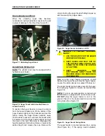
Belts on the new machines have been properly
tensioned at the factory. To re-tension the belts on
a machine which has been in operation.
•
Loosen bolts “B” and “C”. (See
•
Place a scale at the midway point of the
double v-belts on the pulleys.
•
Adjust bolt “A” (See
) until 15
pounds of pull on the scale raises the top
of one double v-belt approximately ¼ inch
above the top of the remaining belts. (See
Figure 36 - Belt Tension Adjustment (Shields
Removed for Clarity).
•
All 4 belts should have the average of ¼
inch deflection at 15-18 pounds.
•
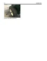
Loosen bolts “E” and “F”. (See
•
Loosen idler bolt “G”
•
Adjust bolt “H” until Hammer mill Jack
Shaft “D” is parallel to Hammer mill
Housing. Measure both sides
•
Tighten bolts “B”, “C”, “E”, and “F”. Lock
adjusting bolts “A” in place with nut.
•
Adjust tension in Main Drive Chain. (See
Previous Section)
Figure 37 - Belt Tension Adjustment Bearing Mount.
½”
A
B
C
F
E
H
G
D