


Doc.-no.: DPC200-MOD_02_EN
Issue: 08/2019
8
OPERATION
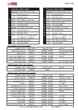
4.4 Electrical connection
1. Unscrew screws of the front cover.
2. Open front cover.
3. Use M16 cable glands for connecting wiring to terminals.
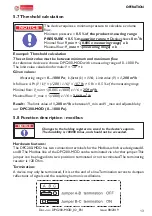
4.5 Zero adjustment
The output signal offset can be zeroed from the outside with a small bar magnet.
Do not use buttons B1 or B2.
Adjustment:
•
Remove the tubing from the pressure
connections.
•
Hold the bar magnet (N/S) as shown here
to the zero point adjustment for a short
period of time to activate an internal reed
switch.
The new zero point will be displayed and
stored.
5. Operation
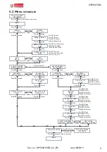
5.1 Start menu
For operating the menu, unscrew the front cover to reach buttons B1 and B2.
N S
+ 15...30 Vdc oder 24 Vac (±15%) Versorgung
- GND
+ 0...10 Vdc Ausgang
- GND
1
2
3
4
5
6
ΔP
DPC200-MOD
Elektrischer Anschluss
B
MODBUS
A
+ 15...30 Vdc or 24 Vac (±15%) supply
- GND
+ 0...10 Vdc output
- GND
1
2
3
4
5
6
ΔP
B
MODBUS
A
DPC200-MOD