


Controls, Indicators, and Connectors
SharpStreamer™ Mini PCIE-7205 Installation and Use (6806800U01A
)
60
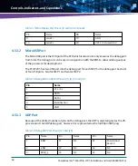
The P7 switch control drives to GPIO inputs on the CPLD and is intended for future
development.The P7 switch control when ON, will isolate the CPLD Programming Header away
from the JTAG chain to be able to program the CPLD
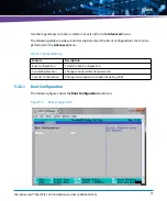
4.4
P8 CPLD Programmer Pinout
The CPLD can be programmed from P8 through the rear of the card. The P8 is not populated,
so a 2x4 header is inserted into the P8 with the other side on the lattice programmer. This is
done to allow programming access with limited space on the top of the card due to the full size
heat sink.
Table 4-3 Pinout for P7 GPIO Switches
Pin
Name
1
GND
2
GND
3
GND
4
GND
5
GND
6
3.3V Pull up
7
JTAG BUFFER DISABLE
8
JUMPER 5
9
JUMPER 4
10
JUMPER 3
11
JUMPER 2
12
JUMPER 1
Table 4-4 CPLD Programming Pinout
Pin
Name
1
CPLD TCK
2
GND
3
CPLD TMS
Summary of Contents for SharpStreamer Mini PCIE-7205
Page 8: ...SharpStreamer Mini PCIE 7205 Installation and Use 6806800U01A 8 List of Tables ...
Page 10: ...SharpStreamer Mini PCIE 7205 Installation and Use 6806800U01A 10 List of Figures ...
Page 18: ...SharpStreamer Mini PCIE 7205 Installation and Use 6806800U01A Safety Notes 18 ...
Page 22: ...SharpStreamer Mini PCIE 7205 Installation and Use 6806800U01A Sicherheitshinweise 22 ...
Page 52: ...Functional Description SharpStreamer Mini PCIE 7205 Installation and Use 6806800U01A 52 ...
Page 106: ...Utilities and Applications SharpStreamer Mini PCIE 7205 Installation and Use 6806800U01A 106 ...
Page 108: ...Related Documentation SharpStreamer Mini PCIE 7205 Installation and Use 6806800U01A 108 ...
Page 109: ......


