3
IMPORTANT SAFETY INSTRUCTIONS – READ FIRST
.......................................................... 2
OVERVIEW
.................................................................................................................................................. 4
Features ......................................................................................................................................................... 4
INSTALLATION
.......................................................................................................................................... 5
AC Power Hookup.......................................................................................................................................... 5
Input/Output Connections............................................................................................................................... 5
Mono 3-Way Configuration ............................................................................................................................. 5
Connections: .............................................................................................................................................. 5
Controls: ..................................................................................................................................................... 5
OPERATION
.................................................................................................................................................. 6
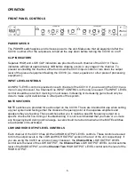
FRONT PANEL CONTROLS
................................................................................................................. 6
Power Switch .............................................................................................................................................. 6
Clip Indicators ............................................................................................................................................. 6
Input Level Controls .................................................................................................................................... 6
Mute Switches ............................................................................................................................................ 6
Low And High Output Level Controls .......................................................................................................... 6
Crossover Frequency Controls And Range Switches ................................................................................. 7
REAR PANEL CONNECTORS and CONTROLS
............................................................................. 7
XLR Jacks .................................................................................................................................................. 7
1/4” Phone Jacks ........................................................................................................................................ 7
Mono/Stereo Mode Switch .......................................................................................................................... 7
APPLICATIONS
......................................................................................................................................... 8
Typical Setup ................................................................................................................................................. 8
Signal Flow .................................................................................................................................................... 8
Initial Setup Tips ............................................................................................................................................ 8
WARRANTY INFORMATION
................................................................................................................ 9
Limited Warranty ............................................................................................................................................ 9
Exclusions .......................................................................................................
Error! Bookmark not defined.
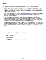
SERVICE
.................................................................................................................................................... 10
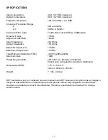
SPECIFICATIONS
................................................................................................................................... 11


