background image

Installing the Telephony Modem USB Drivers  

 3-3

Telephony Modem Installation Guide Release 4 Standard 3.0 Aug 2004

Procedure 3-1 (continued)

Installing USB Drivers

5

Click the 

Next

 button. At this point, Windows XP will proceed through steps 

6-8. Windows XP users may go to step 9.

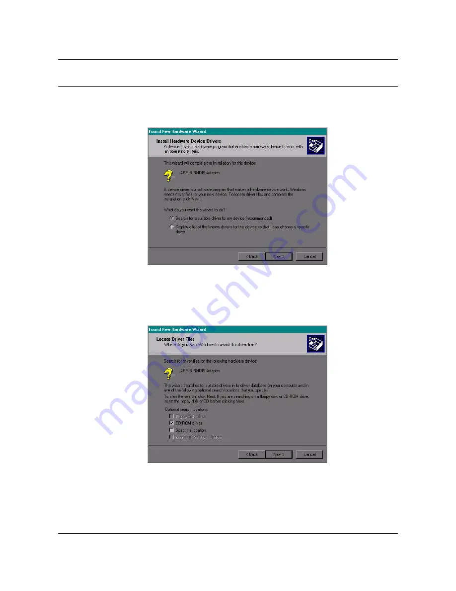
The wizard prompts you for the location of the drivers.

Note: 

The dialog indicates that the wizard is looking for the ARRIS RNDIS 

(Remote Network Device Interface Specification) driver for the Telephony 
Modem.

6

Select “Search for a suitable driver...”, then click the 

Next

 button. 

The wizard displays a list of search options.

—continued—

Summary of Contents for TM02AA104

Page 1: ...stone Telephony Modem on a Windows system 4 Using the Telephony Modem This chapter describes the controls and features available on the Model 4 Touch stone Telephony Modems and covers basic troubleshooting procedures 5 Troubleshooting the Telephony Modem This chapter identifies problems that might occur following the Telephony Modem installation These troubleshooting procedures provide corrective ...

Page 2: ...ii Touchstone Telephony ARSVD00770 Standard 2 0 Aug 2004 ...

Page 3: ...ease 4 Standard 3 0 Aug 2004 iii Publication history August 2004 Release 4 0 Standard 3 0 of the document to include information relating to the new variants as well as the 402G and 402H models May 2004 Standard 2 0 version of the document ...

Page 4: ...iv Publication history Touchstone ARSVD00770 Release 4 Standard 3 0 Aug 2004 ...

Page 5: ...2 1 Requirements 2 1 List of materials 2 1 Tools and Materials 2 1 Overview 2 2 Location 2 3 Procedure 2 1 Installing the Batteries TM402P and TM402Q models 2 4 Procedure 2 2 Installing the Battery TM402G and TM402H models 2 6 Procedure 2 3 Mounting the Telephony Modem 2 8 Procedure 2 4 Connecting the Telephony Modem 2 11 Installing the Telephony Modem USB Drivers 3 1 Requirements 3 1 Procedure 3 ...

Page 6: ...ing a Backup Battery Pack TM402P and TM402Q models 4 8 Procedure 4 2 Replacing a Backup Battery Pack TM402G and TM402H models 4 10 Troubleshooting the Telephony Modem 5 1 Procedure 5 1 Troubleshooting the Power Connection 5 2 Procedure 5 2 Troubleshooting the Ethernet Connection 5 3 Procedure 5 3 Troubleshooting USB Connection 5 4 Procedure 5 4 Troubleshooting Telephone Connection 5 5 ...

Page 7: ...up TM402B CE Euro DOCSIS 220 240V AC power no battery backup TM402G CE North American DOCSIS 220 240V AC power with Li Ion battery backup TM402G NA North American DOCSIS 100 120V AC power with Li Ion battery backup TM402H CE Euro DOCSIS 220 240V AC power with Li Ion battery backup TM402P CE North American DOCSIS 220 240V AC power with extended Li Ion battery backup TM402P NA North American DOCSIS ...

Page 8: ...ternational Inc 220 240 VAC 50 Hz 0 5 A MAX CM All Rights Reserved Model TM402G 110 P N TM02AC104 DANGER Mains voltages inside this unit No user serviceable parts inside Refer service to qualified personnel only Made in Country Patents Pending Copyright 2004 ARRIS International Inc FOR HOME OR OFFICE USE 100 120 VAC 50 60 Hz 0 5 A MAX C CM All Rights Reserved Model TM402H 220 P N TM02BD104 DANGER ...

Page 9: ...oint within an equilateral triangle is intended to alert the user to the presence of important operating and maintenance instructions in the literature accompanying the appliance Alternating Current A terminal to which or from which an alternating sinewave current or voltage may be applied or supplied Direct Current A terminal to which or from which a direct current or voltage may be applied or su...

Page 10: ...tallation Operation is subject to the following two conditions 1 this device may not cause harmful interference and 2 this device may accept any interference that may cause undesired operations This equipment generates uses and can radiate radio frequency energy and if not installed and used in accordance with the instructions may cause harmful interference to radio communications However there is...

Page 11: ...es between system components To ensure compliance with FCC regulation the user must use these cables and install them properly Product Safety UL listed per UL60950 European Compliance This product complies with the provisions of the Electromagnetic Compatibility EMC Directive 89 336 EEC the Amending Directive 92 31 EEC the Low Voltage Directive 73 23 EEC and the CE Marking Directive 93 68 EEC As s...

Page 12: ...xii About this document Touchstone ARSVD00770 Release 4 Standard 3 0 Aug 2004 ...

Page 13: ... 240V 50Hz 0 5A max Physical Specifications Weight Telephony Modem TM402P TM402Q without batteries 1 56 lb 0 71 kg Telephony Modem TM402G TM402H without battery 1 51 lb 0 68 kg Telephony Modem TM402P TM402Q maximum two batteries 2 36 lb 1 07 kg Telephony Modem TM402G TM402H with battery 1 88 lb 0 85 kg Battery 0 40 lb 0 18 kg Telephony Modem TM402A TM402B 1 05 lb 47 kg Table 1 1 Physical Dimension...

Page 14: ...ations Subscriber Telephony Interface Two lines of plain old telephone service POTS Loop Current Normal mode 20 mA minimum Boost high current mode 40 mA nominal short circuit Maximum Loop 1500 ft 26 AWG Talk Battery 44V DC to 53V DC idle state Loading 10 REN total 5 REN per line individual line load depends on country template in use Applicable Standards TM402A NA TM402A CE TM402P NA TM402P CE TM4...

Page 15: ...ins the following items Telephony Modem Zero one or two Li Ion battery packs battery backup models only Power cord CD containing USB drivers and this manual Quick Start Guide Initial Battery Installation Guide battery backup models only Product Safety and Conformance Guide and Wall Mounting Template and Instructions Ethernet and USB cables Two 6 screws Tools and Materials Make sure you have the fo...

Page 16: ...plate printed on the Wall Mounting Template and Instructions sheet transparent tape for temporarily securing the mounting template to the wall For desktop mounting a torque limiting wrench for connecting the cable F connector spectrum analyzer for checking RF levels optional a location on a desk that will allow for proper cable clearance and ventilation for the unit In addition leave enough slack ...

Page 17: ...bottom of the Telephony Modem and any flooring or shelving underneath to allow access to cabling with enough room around the unit that the battery compartment can be accessed and a battery or batteries replaced battery backup models only How to use this chapter The following table lists the procedures in this chapter Perform them in the order shown Procedure Page Installing the Batteries TM402P an...

Page 18: ...es Use this procedure to install the backup batteries Action 1 Pull down on the two latches holding the battery door on the bottom of the Telephony Modem and pull the door toward you Set the door aside 2 Hold each battery by its pull tab and insert the batteries into the bay The following photo shows the proper orientation Batteries will not insert completely into the Telephony Modem if not orient...

Page 19: ...Battery bay 2 is reserved for a second battery pack 4 Replace the door To do so place the tabs of the battery door into the slot on the telephony modem battery compartment Rotate the door away from you until the two latches snap back into place It is normal for the Battery 1 and Battery 2 LEDs to flash after initial installation of the battery to show that the battery ies are charging Note The TM4...

Page 20: ...ttery Use this procedure to install the backup battery Action 1 Pull down on the latch holding the battery door on the bottom of the Telephony Modem and pull the door toward you Set the door aside 2 Hold the battery by its pull tab and insert the battery into the bay The following photo shows the proper orientation The battery will not insert completely into the Telephony Modem if not oriented cor...

Page 21: ...te 2 It is normal for the Battery LED to flash after initial installation of the battery to show that the battery is charging 4 Replace the door To do so place the tabs of the battery door into the slot on the Telephony Modem battery compartment Rotate the door away from you until the latch snaps back into place Note The TM402G and TM402H models use a lithium ion battery pack The battery does cont...

Page 22: ...select a location within 5 feet 1 6m of an unswitched AC outlet Leave sufficient clearance around the Telephony Modem and any flooring or shelving underneath to allow access to cabling In addition leave enough slack in all cables so that the Telephony Modem can be removed for maintenance without disconnecting cables There must also be enough room around the Telephony Modem to allow for battery rep...

Page 23: ...he screws leaving a gap of about 3 mm 0 12 inches between the screw head and the wall 6 Lift the Telephony Modem into position Slip the large end of the mounting slots in the back of the Telephony Modem over the screws then slide the vertically or horizontally until the narrow end of the keyhole slot contacts the screw shaft 7 Proceed to Connecting the Telephony Modem on page 2 11 Desktop mounting...

Page 24: ...g the Telephony Modem Note When mounting the TM402A or TM402B unit vertically first you must engage the stand on the bottom of the unit To do so pull the oval foot out slightly twist the foot as shown below and place the Telephony Modem in the desired location 10 Proceed to Connecting the Telephony Modem on page 2 11 end ...

Page 25: ...errors or dropped calls Telephony Modem Rear Panels The Telephony modem models TM402G TM402H TM402P and TM402Q have the following rear connections A Tel 1 Tel 2 plug the first line of telephone service here If a 4 conductor cable is used this connector will support both lines of service B Tel 2 used for the second line of telephone service C USB Universal Serial Bus use this connection to connect ...

Page 26: ... the Telephony Modem to the customer s equipment via the Ethernet cable F RF connection for network coax cable The following shows the rear panel of the Telephony Modem 402P and 402Q The following shows the rear panel of the Telephony Modem 402A and 402B There are two variants both are functionally equivalent although the rear panels differ continued C B A E D F C B A D E F C B A D E F ...

Page 27: ...ck of the Telephony Modem and the opposite end into a convenient wall outlet For the TM402A and TM402B models connect the power cord from the supplied power adapter to the power jack on the back of the Telephony Modem Then connect the additional power cord to the supplied power adapter and finally into a convenient wall outlet 4 After the coax cable and power have been connected Making USB Connect...

Page 28: ...del TM402A or TM402B go to step 12 10 Connect the other end of the cable to the connection on the modem labeled Tel 1 Tel2 using a standard RJ 11 connector 11 If a second line of telephony service is required do one of the following If you use a 4 conductor cable you can use the Tel1 Tel2 connector to provide access to both lines The red and green wires provide the first line and the yellow and bl...

Page 29: ...lly detects the hardware and attempts to install the drivers Requirements Make sure you have the following before attempting to install the USB drivers PC with CD ROM drive at least one free USB port one of Windows 98SE Windows 2000 Windows ME or Windows XP Windows 95 and Windows NT are not supported ARRIS USB Driver CD USB A B cable of appropriate length IP address subnet gateway and DNS informat...

Page 30: ...edure 1 Make sure the Telephony Modem is on the Power light should be on If not connect the power supply as described in Connecting the Telephony Modem on page 2 11 2 Insert the Touchstone USB Drivers CD 3 Plug the appropriate end of the USB cable into the Telephony Modem and the other end into the computer s USB port The PC displays the following window 4 Wait for the system to start the installa...

Page 31: ...Windows XP will proceed through steps 6 8 Windows XP users may go to step 9 The wizard prompts you for the location of the drivers Note The dialog indicates that the wizard is looking for the ARRIS RNDIS Remote Network Device Interface Specification driver for the Telephony Modem 6 Select Search for a suitable driver then click the Next button The wizard displays a list of search options continued...

Page 32: ...ot find the CD drive and the CD is inserted properly follow these steps a On the Windows desktop open My Computer and note the letter of the Compact Disc or CD ROM drive on most systems the CD drive is at D or E b Return to the Found New Hardware Wizard and click the Back button The wizard displays the previous screen shown in step 6 c Select Specify a Location then choose the drive letter that co...

Page 33: ... Modem Installation Guide Release 4 Standard 3 0 Aug 2004 Procedure 3 1 continued Installing USB Drivers 8 Click the Next button The wizard installs the drivers then displays a window indicating that the installation is complete 9 Click the Finish button end ...

Page 34: ...3 6 Installing the Telephony Modem USB Drivers Touchstone ARSVD00770 Release 4 Standard 3 0 Aug 2004 ...

Page 35: ...ng factors can affect hold up times The age and temperature of the battery pack hold up times will decrease with increasing battery age and at higher temperatures Battery charge level when AC power is lost Activity level of the Telephony Modem data transfer additional lines off hook boosted loop current 40mA continuous ringing etc can reduce the hold up time About the Backup Battery TM402P TM402Q ...

Page 36: ...t the battery pack is partially discharged This discharge period will last less than 11 hours Following the discharge period the Telephony Modem will fully recharge the battery pack see Battery Charging When two battery packs are present TM402P and TM402Q models only the Telephony Modem will not begin discharging the second pack until the first pack has been discharged and fully recharged This ens...

Page 37: ...a first line of telephony service Telephone 2 indicates the status of a second line of telephony service Battery 1 indicates status of the primary battery battery backup models only Note The TM402G and TM402H models only have one battery backup available The LED indicator for these models reads Battery There is no Battery 2 LED Battery 2 indicates the status of the secondary battery battery backup...

Page 38: ...Off Off Off Off Off 1 Self Test Flash3 Flash Flash Flash Flash Flash Flash Flash Flash 2 Downstream Scan Sync On Flash Off Off Off Off Off Off Off 3 Upstream Ranging On On Flash Off Off Off Off Off Off 4 DOCSIS DHCP TFTP On On On Flash Off Off Off Off Off CM Normal Operation 5 Telephony DHCP On On On On On Flash Off Off Off 6 Telephony SNMP TFTP On On On On On Off Flash Off Off 7 Telephony RSIP On...

Page 39: ...net port Flash CPE activity on Ethernet port On Service available phone on hook Off Service not available Flash Phone off hook Slow Flash3 Line Card Error On Battery good Off Battery bad or missing Flash Battery low AC Power Fail Flash Off Off Off Off On Service available phone on hook Off Service not available Flash Phone off hook Slow Flash Line Card Error Off Battery good bador missing Flash Ba...

Page 40: ... but not to the internet through the RF interface The current Standby setting is stored in non volatile memory If the Telephony Modem is reset or loses battery power battery backup units or AC power non battery backup units it returns to its previous standby state The Standby button has no effect before the modem has registered Telephone service is NOT affected by the Standby mode The following ta...

Page 41: ...ower up state The Reset button is recessed to prevent accidental resets Use a pointed non metallic object to press the button The following diagram shows the location of the Reset button for the TM402P and TM402Q The following diagrams show the location of the Reset button for the TM402A and TM402B The following diagram shows the location of the Reset button for the TM402G and TM402H Reset button ...

Page 42: ...for this procedure one or two replacement battery pack s ARRIS order number 710476 contact your next level of support for a list of currently available battery suppliers Action 1 Pull down on the two latches holding the battery door on the bottom of the Telephony Modem and pull the door toward you Set the door aside The batteries are now accessible 2 Lift up the latch and pull the battery pack out...

Page 43: ...se 4 Standard 3 0 Aug 2004 Note The TM402P and TM402Q models use one or two lithium ion battery pack s This battery does contain precious material there may be some benefit in recycling Please dispose of the battery responsibly and in accordance with local ordinances end ...

Page 44: ...ct your next level of support for a list of currently available battery suppliers Action 1 Pull down on the latch holding the battery door on the bottom of the Telephony Modem and pull the door toward you Set the door aside The battery is now accessible 2 Lift up the latch and pull the battery pack out of the bay 3 Install new battery pack as described in Installing the Battery TM402G and TM402H m...

Page 45: ...Telephony Modem 5 This chapter identifies problems that might occur following the Telephony Modem installation These troubleshooting procedures provide corrective actions that may be required When performing troubleshooting actions continue through each step until the trouble condition clears ...

Page 46: ...elephony Modem does not have power none of the LED indicators are lit Action 1 Make sure that all cabling is properly connected 2 Make sure that the outlet to which the power supply is plugged into is not controlled by a switch If an unswitched outlet is not available make sure the wall switch is on 3 Replace the unit 4 Call your next level of support end ...

Page 47: ... the DS US and Online LEDs are lit 3 Ensure Ethernet cable is plugged into the Telephony Modem and the corresponding Ethernet port on the customer s computer 4 If the Link LED is off Check the Ethernet cable to ensure there are no cracks If using a powered hub is the hub receiving power and turned on Ensure the correct Ethernet cable is being used Refer to Making Ethernet Connections on page 2 14 ...

Page 48: ...he customer s computer 4 Verify that the PC is running one of Windows 98SE Windows 2000 Windows ME or Windows XP Windows 95 and Windows NT are not supported 5 Restart the PC 6 Push the Reset button on the back panel of the Telephony Modem Note The Reset button is recessed to prevent accidental resets Use a pen tip or other sharp non metallic object to push the button 7 Replace the USB cable 8 For ...

Page 49: ...he necessary people to provision the line 4 Check that the cables from the Telephony Modem to the phone are connected tightly and not cracked cut or otherwise compromised 5 Make sure all phones are hung up properly 6 On remote and powered phones check the power and battery status of the phone s 7 If a fast busy is heard the call server is in need of attention 8 Call your next level of support end ...

Page 50: ...5 6 Troubleshooting the Telephony Modem Touchstone ARSVD00770 Release 4 Standard 3 0 Aug 2004 ...

Page 51: ......

Page 52: ...ment design or program components as progress in engineering manufacturing methods or other circumstances may warrant ARRIS ARRIS Interactive and Touchstone Telephony are trademarks of ARRIS Licensing Company Cornerstone is a registered trademark of ARRIS Licensing Company All other trademarks and registered trademarks are the property of their respective holders ARSVD00770 Release 4 Standard 3 0 ...

Reviews: