background image

73 

S

OFTWARE


The CD-Rom provided includes two software programmes that allow the user to perform UPS monitoring, control 
and configuration operations. 


M

ONITORING AND

 AND CON

 CONTROL SOFTWARE


The 

Watch & Save 3000

  software  ensures  efficient  and  intuitive 

UPS  management

,  by  displaying  all  the 

most important information such as input voltage, applied load, battery capacity, etc. 

It can also automatically execute programmed shutdown/start-up operations, shutdown of the O.S., sending of e-
mails, sms and network messages when specific user-selected events occur.  
 

Installation Operations: 

x

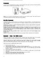
  Connect the UPS USB port to a USB port on the PC using the cable provided. 

x

  Insert the CD-Rom and select the operating system required. 

x

  Follow the installation instructions. 

x

  For more detailed information on the installation and use of the software, refer to the software manual in the 

Manuals

 folder on the CD-Rom provided. 

Visit the manufacturer’s web site to check whether a more recent version of the software is available. 


C

ONFIGURATION 

S

OFTWARE


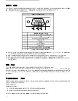
UPSTools

 software allows the user to configure the UPS and provides a full view of the system parameters and 

status through the USB port.  
Refer to the paragraph 

UPS Configuration

 for a list of the possible configurations available.  


Installation Operations: 

x

  Connect the UPS USB port to the USB port on the PC using the cable provided.  

x

  Follow  the  installation  instructions  given  in  the  software  manual  in  the 

UPSTools

  folder  on  the  CD-Rom 

provided.  

Visit the manufacturer’s web site to check whether a more recent version of the software is available. 


Summary of Contents for Spring 500-3000VA

Page 1: ...UNINTERRUPTIBLE POWER SUPPLY LINE INTERACTIVE 500 3000VA BATTERY BOX Manuale d uso User s manual Bedienungsanleitung...

Page 2: ......

Page 3: ...egare il cavo di alimentazione Ambiente operativo manutenzione e guasti L UPS funziona a tensione pericolose Ogni riparazione deve essere effettuata solamente da personale qualificato Attenzione Risch...

Page 4: ...order to fully disconnect the UPS system first press the OFF switch then disconnect the mains Maintenance servicing and faults The UPS system operates with hazardous voltages Repairs may be carried ou...

Page 5: ...dr cken und dann die Netzkabel vom Netz trennen Wartung Service und St rungen Die USV arbeitet mit gef hrlichen Spannungen Reparaturen d rfen nur von qualifizierten Technikern vorgenommen werden Achtu...

Page 6: ...e d alimentation Environnement de travail entretien et pannes L ASI fonctionne sous des tensions dangereuses Toute r paration doit tre effectu e exclusivement par un personnel qualifi Attention Risque...

Page 7: ...ble de alimentaci n Entorno de funcionamiento mantenimiento y aver as El SAI funciona con tensiones peligrosas Cualquier reparaci n debe ser realizada nicamente por personal cualificado Atenci n Riesg...

Page 8: ...sladden f r att helt och h llet koppla ur UPS enheten Underh ll service och fel UPS enheten fungerar under farlig sp nning Reparationer f r endast utf ras av beh rig underh llspersonal Varning risk f...

Page 9: ...t op de OFF schakelaar te drukken en daarna de hoofdleiding uit te trekken Onderhoud controle en foutmeldingen Het UPS systeem werkt met gevaarlijke voltages Reparaties kunnen uitsluitend uitgevoerd w...

Page 10: ...eiramente o interruptor OFF para ent o desconectar os principais cabos condutores Manuten o assist ncia t cnica e falhas O UPS funciona com tens es de alto risco Consertos somente dever o ser feitos p...

Page 11: ...72 RS232 PORT 72 USB PORT 72 COMMUNICATION SLOT 72 SOFTWARE 73 MONITORING AND CONTROL SOFTWARE 73 CONFIGURATION SOFTWARE 73 TROUBLE SHOOTING 74 BATTERY REPLACEMENT 75 SPRING T 75 SPRING R 76 SPRING R...

Page 12: ...use and install the UPS For information on using and getting the best performance from your UPS this manual should be kept safely in the vicinity of the UPS and CONSULTED BEFORE TAKING ANY ACTION ON...

Page 13: ...other functions should work well such as AVR function in line mode switch on and switch off overload protection FEATURES Sinusoidal output voltage LCD display Microprocessor control that guarantees hi...

Page 14: ...ing W 350 540 740 1050 1350 350 540 740 1050 1540 2100 Output nominal voltage Vac 200 208 220 230 240 Dimensions LxHxD mm 110X235X383 160X235X425 438X44X460 19 x1Ux460 438X88X582 19 x2Ux582 FRONT VIEW...

Page 15: ...53 REAR VIEW Spring 500 800 1100 T Spring 1500 2000 T Spring 500 800 1100 R Spring 1500 RT...

Page 16: ...t 2 Cooling fans 3 Telephone modem protection 4 Input Breaker 5 IEC mains input plug 6 IEC output sockets max 10A 7 Communication expansion slot 8 Battery expansion connector 9 IEC 16A output socket 1...

Page 17: ...packaging is to check the contents The packaging should contain the following UPS IEC 16A Power cord Only for 2200 3000 RT IEC 10A connection cables USB cable Tower stands Only for RT models slide as...

Page 18: ...CAUTION The long term uses at ambient temperature in higher than 25qC which should reduce battery life In addition place the UPS unit away from the monitor at least 20cm to avoid interference UPS SET...

Page 19: ...BATTERY BOX 1 Put the bracketes and the bracket extension together 2 Slide down the UPS and the battery box vertically and put two UPS stands at the end of the tower 3 Place the UPS and battery box in...

Page 20: ...he below steps and charts you can rotate the LCD display A Rack To Tower 1 The UPS is placed by the level pressing the key 2 The LCD display cover can be rotate at 90 angles 3 Tower configuration B To...

Page 21: ...he following procedure to install UPS in a rack 1 Align the mounting ears optional for RT models with screw holes on the side of the UPS 2 Fix the slide to the rack enclosure with screws 3 Insert UPS...

Page 22: ...one wires during a storm NOTICE The protection device limits the effects of an overvoltage but does not guarantee overall protection EMERGENCY POWER O FF EPO SET SET UP UP Spring R and Spring RT serie...

Page 23: ...cable from battery box to the external battery port in the rear of UPS 3 If continuing to add up battery box total capacity max 120Ah repeat above steps Note When the battery box needs for making lon...

Page 24: ...d beep every 4 seconds 3 Reconnect the power cable Normal mains power operation should be restored C OOL START FUNCTION Cool start function enables UPS to be started up when AC utility power is not av...

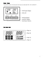
Page 25: ...63 FRONT PANEL There are three buttons on the front panel which have been marked with ON OFF and SELECT LCD TOTAL VIEW...

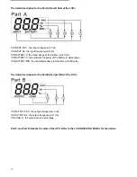
Page 26: ...BATTERY the estimated capacity of the battery in percentage BATTERY MIN the estimated battery remain time unit Minute The detail description for the Part B the right field of the LCD OUTPUT VAC the o...

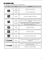
Page 27: ...ular intervals Flashing When operating off battery power the UPS signals that it is about to switch off due to end of discharge In this state it beeps at regular intervals of 1 sec Steady Indicates ba...

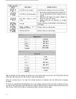
Page 28: ...your local dealer UPS internal fault Please contact your local dealer Table 2 Battery level 0 20 20 40 40 60 60 80 80 100 Tab 3 Load level 0 5 5 25 25 50 50 75 75 102 flashing 102 After overloading th...

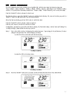
Page 29: ...ks the third nothing blinks When the field are blinking push the ON button to confirm the field Push the SELECT button to choose measure required Push the ON button to confirm the measure choosed Conf...

Page 30: ...tton and the characters INPUT Hz and corresponding measure the blank font of the left field will blink Step 5 Push the SELECT button again and the characters BATTERY V and corresponding measure the bl...

Page 31: ...his measure then the measure of the left field is the Estimate battery runtime Step 9 Push the SELECT button for 3 seconds and the left field of the LCD will blink Push the SELECT button again and the...

Page 32: ...d corresponding measure the blank font of the left field will blink Step 13 Push the ON button then the measure of the right field is the Load percentage The configuration is complete NOTE 1 If the co...

Page 33: ...for warning g If battery is disconnected after battery test buzzer will beep intermittently 1s on 1s off for warning h When buzzer silence function is enabled keeping ON botton pressed for over 3 sec...

Page 34: ...5V 25mA c B L contact closed in battery low status max ratings 25mA 35Vdc Vce sat max 1 5V 25mA d UPS failure Alarm contact closed in UPS failure Alarm status max ratings 25mA 35Vdc Vce sat max 1 5V...

Page 35: ...ing system required x Follow the installation instructions x For more detailed information on the installation and use of the software refer to the software manual in the Manualsfolder on the CD Rom p...

Page 36: ...one of the output sockets Check the output fuse UPS could not provide power to the load Power is not presents on any output sockets 1 Check the connected cable 2 Ensure the load does not exceed the ma...

Page 37: ...pose the batteries in a fire It may explode Do not open or mutilate the batteries Released electrolyte is harmful to the skins and eyes It may be toxic A battery can present a risk of electrical shock...

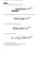
Page 38: ...from the UPS then unscrew the battery bracket from the UPS 3 Remove the battery plate retaining battery stably 4 Pull the battery out onto flat area 5 Slide the new batteries into UPS 6 Reconnect the...

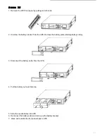
Page 39: ...t from the UPS Remove the battery plate retaining battery stably 3 Disconnect the battery cable from the UPS 4 Pull the battery out onto flat area 5 Slide the new batteries into UPS 6 Reconnect the ba...

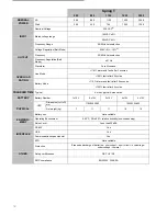
Page 40: ...30 seconds OVERLOAD RATING Battery Mode 120 fault after 40 cycles TRANSFER TIME Typical 4 msec typical 6 msec max BATTERY Battery Number 1x12V 2 x12V 2 x12V 4 x12V 4 x12V Dimension LxHxD mm 110X235X3...

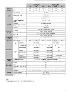
Page 41: ...x6V 3x6V 4x6V 4 x12V 8x12V 8x12V Dimension LxHxD mm 438X44 3X460 19 x1Ux460 438X87 9X582 19 x2Ux582 UPS Net weight kg 12 13 15 29 31 32 Nominal voltage Not availlable Not availlable 96 V Nominal Not a...

Reviews: