Toronto
English
00 18/04/2012
19
PORTUGUESA
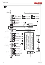
9. Electrical connection (Fig. 12)
- The electrical system must be grounded.
- First of all, make sure that the power supply voltage is that indicated on the rating plate (Fig. 2)
- The unit should be protected upstream using an automatic magnetothermal omnipolar cutoff switch with
appropriate characteristics and that also serves as the general circuit breaker for the line.
- Inform operators of the switch location so that it can be reached quickly in the case of an EMERGENCY.
- To guarantee normal performance, maximum voltage variation must be b/- 6% of the nominal
value.
- Check that the power supply line has cables with an appropriate cross section, that they are protected
against power surges and have a grounding system that conforms to the laws in effect.
- The installer should provide anchoring devices for all cables entering and leaving the unit.
- For power supply lines longer than 4-5m, increase the cable cross section correspondingly.
- In the case that the power supply is interrupted, check that all the electrical devices in the store are able
to start up again without tripping the power surge protection. If not, modify the system so as to create a
lag time for the start up of various devices.
- The installer should provide anchoring devices for all cables entering and leaving the unit.
- The automatic magnetothermal switch should be designed so as to not open the neutral circuit without
simultaneously opening on the phases. In any case, the the opening distance for the contacts must be
at least 3mm.
N.B.All these operations should be performed by specialized technical personnel.
- Temperature probe: NTC IP67 L=4000 cod.04510153.
- Probes S1 - S3 must be fixed in place using terminals and should not be insulated.
- Probe S2 must be fixed in place with contact between the 3rd and 4th tube (never in correspondence
with the fan) using the stainless steel bulb block spring, cod.02230021.
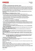
11.Control and adjustment of temperature (Fig. 4)
The refrigeration temperature is controlled using the thermometer (Rif. 5) or with the electronic control
device (OPTIONAL) located on the lower part of the unit (Rif. 5). Normally the controller is set in the
factory during testing, but it is possible to alter programming. To do so, please refer to the instructions
given by the control device manufacturer. If using electronic control devices to adjust the frame heating
wires, these must be operated at full power.
N.B.All these operations should be performed by specialized technical personnel.
12.Loading the unit (Fig. 4 - Fig. 4)
When loading the unit, some important rules must be observed:
- place the merchandise so that it never exceeds the maximum load line (Rif. 6). Exceeding this limit
disturbs proper air circulation, causing an increase in the temperature of the merchandise and the
formation of ice on the evaporator;
- placing the merchandise to avoid empty areas, guarantees that the unit will perform at its best.
- it is recommended that merchandise that has stayed longer
in the unit be consumed before that which
was placed more recently (rotation of foodstuffs)
- The maximum allowable load for the tank is
300 kg/m
2
12_1.Loading the unit for ice cream and frozen food
- decrease as much as possible the time that frozen food is subject to room temperature and humidity in
order to avoid the formation of frost on boxes, which after insertion into the unit, may stick to each other
and to the grills on the bottom.
- limit the time the doors are open to 2 - 3 minutes
1
02940652
8
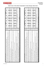
Handrail alignment pin D 4
7
04711098
4
TCEI M8X25 screw
2
04711030
2
TCEI M8X80 screw
8
04230400
2
M6 Hex Nut
3
04711041
1
TCEI M8X50 screw
9
04480103
4
Washer D 6x12
4
04230600
7
M8 Hex nut
10
02940045
2
Light alignment pin D 3
5
04711040
4
TCEI M8X35 screw
11
04715051
3
TC M5X25 screw
6
04480112
8
Washer D 8.5x24
12
04231100
3
M5 Hex nut
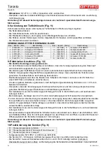
S1
Air delivery control probe
S2
End defrost thermostat control probe
S3
Air intake control probe


