ACM-IP2 ANALOGUE SUBSYSTEMS MODULE
User Manual
armtel.com
page 15/28
© Armtel
ENG
2.2 Preparation for use
The following operations should be performed in preparation for ACM-IP2 unit
preparation for use:
−
removing ACM-IP2 from the shipping container;
−
removing ACM-IP2 from the customer package;
−
check the scope of supply of ACM-IP2 according to product passport;
−
inspect ACM-IP2 enclosure visually, no mechanical damages (cracks, dents, etc.)
on the enclosure, board and elements are allowed;
−
install ACM-IP2 at the operation site (click on the DIN-rail). The location in the
cabinet should be chosen taking into account the convenience of access to the
module for connecting the power and communication wires, as well as for
maintenance. In the same way, install ADSL-IP2 Adapter in ACM-IP2 version of
RMLT.465275.006-01 in the cabinet.
2.3 Installation, connection and dismantling
2.3.1 ACM-IP2 version of RMLT.465275.006 is connected via 100BaseT Ethernet
interface. The on-site connection is carried out using multi-wire UTP type cable, crimped
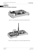
with RJ-45 plugs, which is connected to X1 socket (or to X2 socket) of RJ-45 in accordance
with Figure 2. On the other side, the cable is connected to a network unit with PoE plus
injector function. For version ACM-IP2 RMLT.465275.006-01, it is necessary to connect the
external power to X21 socket and connect ADSL-IP2 Adapter to X19 socket in accordance
with Figure 2 with the cable from the adapter package. If you are using ADSL line, connect
ADSL-IP2 main cable with RJ-12 plug to X25 socket of the ADSL-IP2 module or configure a
Wi-Fi router by contacting the network provider.
100BaseT Ethernet interface in this case is connected to either DSLAM IP router or
Wi-Fi router.
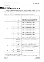
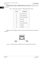
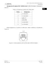
Designation and external appearance of outputs of 100BaseT Ethernet RJ-45 socket for
ACM-IP2 and RJ-12 of ADSL-IP2 Adapter are given in Appendix A.
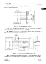
2.3.2 An analog terminal unit is connected to the X3 (or X4), X11 connectors. Connection
examples are given in Appendix A. Connection to terminal units must be performed with a
multicore (four or eight-wire) cable with a cross section not less than 0.12 mm
2
. Before connection,
the cable ends should be stripped from insulation for the length of 5 mm, tin-coated and are
connected to the return (cable) parts of the dockets installed on the unit.


