


Page 9 of 18
Issue 1324
507120-01
Supply and return duct system must be adequately sized
to meet the system’s air requirements and static pressure
capabilities. The duct system should be insulated with
a minimum of 1” thick insulation with a vapor barrier in
conditioned areas or 2” minimum in unconditioned areas.
Supply plenum should be the same size as the flangedopening
provided around the blower outlet and should extend at
least 3 ft. from the air handler before turning or branching
off plenum into duct runs. The plenum forms an extension
of the blower housing and minimizes air expansion losses
from the blower.
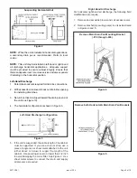
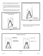
INSTALLING DUCT SYSTEM
Install the conditioned air plenum, ducts and air filters (not
provided) in accordance with NFPA 90B Standard for the
Installation of Warm Air Heating and Air-Conditioning
Systems (latest edition).
Connect supply air duct to the flange on top of the air handler.
If an isolation connector is used, it must be nonflammable.
A return air duct system is recommended. If the unit is
installed in a confined space or closet, a return connection
must be run, full size, to a location outside the closet.
Connecting Refrigerant Lines
Refrigerant lines must be connected by a qualified technician
in accordance with established procedures.
1.
Route the suction and liquid lines from the fittings
on the indoor coil to the fittings on the outdoor unit.
Run the lines in as direct a path as possible avoiding
unnecessary turns and bends.
2. Make sure that the suction line is insulated over the
entire exposed length and that neither suction nor liquid
lines are in direct contact with floors, walls, duct system,
floor joists, or other piping.
3. Connect the suction and liquid lines to the evaporator
coil.
4. To avoid damaging the rubber grommets in the cabinet
while brazing, slide the rubber grommets over the
refrigerant lines until they are away from the heat
source.
5. Braze using an alloy of silver or copper and phosphorus
with a melting point above 100°F.
NOTE:
Do not use soft solder.
6. Reinstall the rubber grommets after brazing is finished.
7. Make sure outdoor unit has been put in place according
to the Installation Instructions and is connected to the
refrigerant lines.
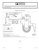
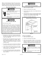
Sealing the Unit
Seal the unit so that warm air is not allowed into the cabinet.
Warm air introduces moisture, which results in water blow-
off problems. This is especially important when the unit is
installed in an unconditioned area.
Refrigerant lines must be clean, dehydrated, refrigerant-
grade copper lines. Air handler coils should be installed
only with specified line sizes for approved system
combinations.
Handle the refrigerant lines gently during the installation
process. Sharp bends or possible kinking in the lines
will cause a restriction.
Do not remove the caps from the lines or system
connection points until connections are ready to be
completed.
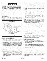
IMPORTANT
There must be an airtight seal between the bottom
of the air handler and the return air plenum. Use
fiberglass sealing strips, caulking, or equivalent sealing
method between the plenum and the air handler
cabinet to ensure a tight seal. Return air must not
be drawn from a room where this air handler or any
gas-fueled appliance (ie., water heater), or carbon
monoxide-producing device (ie., wood fireplace) is
installed.
WARNING
When sealing the cabinet, be sure to seal closed any
space around the holes where the drain lines exit the
cabinet using duct tape and/or Permagum. Warm air
must not be allowed to enter through any gaps or holes
in the cabinet.
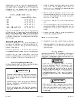
IMPORTANT
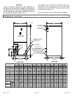
Unit Air Filter Size Chart
Model
Nominal Filter Size
-018
12” X 20” X 1
-024
15” X 20” X 1
-036
18” X 20” X 1
-042,-048 and -060 18” X 24” X 1