


Issue 1324
507120-01
Page 12 of 18
Airflow - Cooling Blower Speed
The cooling blower speed is factory configured to provide
correct airflow for an outdoor unit that matches the maximum
cooling capacity rating of the air handler.
If the outdoor unit is smaller than the maximum cooling
capacity rating for the air handler, the cooling blower speed
may need to be changed. Refer to blower performance
chart, Table 2.
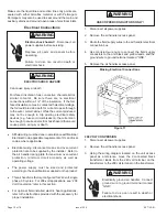
1. Disconnect all power supplies.
2. Remove the air handler access panel.
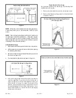
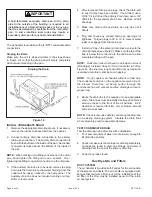
3. Locate pin number 2 on the blower relay. Two black
wires are connected to this terminal pin. One connects
to pin number 5 on the blower relay, one connects to an
in-line splice connecting to a red wire.
4. Remove the wire going to the 4-pin blower motor
connector from the splice.
5. Connect the blower lead [Red (La), Black (HI)] onto the
splice from the 4-pin blower motor connector.
NOTE:
Reuse the factory-installed plastic cap on whichever
wire is not used.
6.
Replace all panels.
7. Reconnect power.
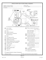
CHANGE BLOWER SPEED
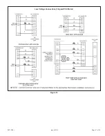
NOTE:
Refer to wiring diagram located on the unit access
panel and blower performance (Table 2).
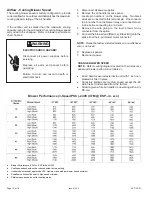
•
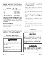
All air data measured external to unit with 1 inch non-
pleated air filter in place.
•
All factory settings are medium speed except the -48
which is set to low speed from the factory.
•
All data given while air handler is operating with a dry
DX coil.
Blower Performance (3-Speed PSC) -240V (CFM @ ESP. -in. w.c.)
•
Blower Performance (CFM vs. ESP inches H2O)
•
Cooling speeds should not be reduced below factory setting.
•
Units with electric heat approved at 0.5” maximum and medium blower speed minimum.
•
Downflow units should be set to high speed minimum.
•
Different speeds can be set for heating mode.
ELECTRIC SHOCK HAZARD!
Disconnect all power supplies before
servicing.
Replace all parts and panels before
operating.
Failure to do so can result in death or
electrical shock.
WARNING


