PDS-32/42/46/47/52/55
www.
Armagard
.com
Installation Manual Page |
8
Toll Free (US):
1-866-434-0807
Call (UK):
0121-608-7210
M6 x 16 Bolts
x6
M6 x 16 Bolts
x6
Standard
enclosure
wall bracket
x2
15 deg enclosure
wall Bracket
(handed)
x2
Wall bracket x 1
Enclosure x1
Optional cealing mount
brackets
LCD Mounting
bracket
x2
Reversible
bracket x2
Keys
x4
Standard parts
Double ceiling
bracket x 1
Single ceiling
bracket x 1
M6 x 16 Bolts
x6
M6 x 16 Bolts
x6
Standard
enclosure
wall bracket
x2
15 deg enclosure
wall Bracket
(handed)
x2
Wall bracket x 1
Enclosure x1
Optional cealing mount
brackets
LCD Mounting
bracket
x2
Reversible
bracket x2
Keys
x4
Standard parts
Double ceiling
bracket x 1
Single ceiling
bracket x 1
M6 x 16 Bolts
x6
M6 x 16 Bolts
x6
Standard
enclosure
wall bracket
x2
15 deg enclosure
wall Bracket
(handed)
x2
Wall bracket x 1
Enclosure x1
Optional cealing mount
brackets
LCD Mounting
bracket
x2
Reversible
bracket x2
Keys
x4
Standard parts
Double ceiling
bracket x 1
Single ceiling
bracket x 1
STEP
18
:
Check all apparatus for the installation is present and correct (Figure
13
)
– Depending on
your setup you will have either
(2)
flat or
(2)
15 degree wall brackets.
M8 x 16 Bolts x (4-6)
M8 x 16 Washers x (4-6)
Figure13
STEP
19
: Position your enclosure for clear access to its back panel and remove the fitted washers
and bolts.
Figure14
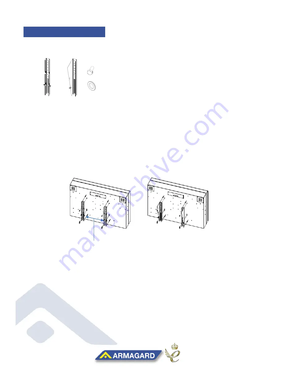
STEP
21
: For a balanced unit, align the centre hole of the bracket with the halfway line of your
display (Figure14). Making sure the mounting slots are fitted to the lower half of the unit,
then equally space and secure the brackets with M8 washers and bolts.
STEP
20
: Using a measuring tape, determine the halfway line of the unit from top to bottom.
ENCLOSURE BRACKETS
Mounting slots on
the lower half