ARITERM SWEDEN AB
Installation, Operation and Maintenance - 2007.10.26- 6/12
Th
e boiler shall be positioned and installed according to the building rules in force.
Before installing the boiler, the chimney must be controlled for underpressure and
possible risk of condensation. It is possible that an air draught compensator has to be
installed. Inner pipe is recommended for minimizing the risk of condensation.
Space needed for installation: Minimum clearance in front of the boiler (burner
included) is 1000 mm. Clearence on the top shall be at least 0,5 m. By the other side
of the boiler clearence shall be at least 0,8 m. Th
e boiler must be level. If the fl oor is
uneven, adjustments can be made with the help of four adjusting bolts (enclosed with
the boiler) that shall be fi tted to the bottom plate of the boiler.
Th
e air intake duct to the boiler room must have at least the same area as the fl ues.
Chimney installation
To embed the angular tube in the chimney, proceed according to the drawing below.
If the tube is embedded as described, you will be able to avoid soot leakage when the
chimney is being swept.
Flue connection and combustion air intake
Th
e combination fl ue of the boiler allows for connection towards the top as well as
to the rear. Boiler cement is suitable for sealing. Recommended fl ue gas requirements
for B 50: brick chimney lined with a Ø 150 mm acid proof thin-walled tube
or an acid proof Ø 150 mm element chimney. Recommended underpressure in the
chimney is 25 Pa. Th
e height of the gas fl ue shall be dimensioned according to the
building’s requirements, but should be at least 6 m. If condensation water comes out of
the fl ue, a condensate drain pan shall be installed in the lower portion of the chimney.
Th
e combustion air intake must not be covered.
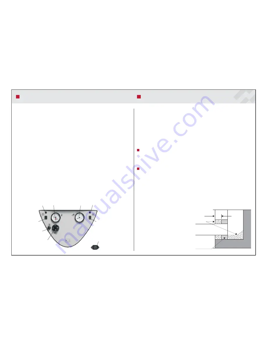
1. Regulating thermostat
Adjustment of operating temperature for pellet burner
2. Overheating protection, burner
- Press the button to reset the overheating cut-out. Before reset,
check that there is water in the boiler and that the operating thermostat
works correctly. If you cannot reset the overheat protection, please
contact a qualied installation contractor.
3. Th
ermometer / Pressure gauge
- Shows water pressure and water temperature at the top of the
boiler. Due to the stratication of water, boiler temperature varies
considerably within the boiler; the lowest water temperature is measured
at the bottom and the highest at the top.
4.
Flue gas thermometer
- Displays temperature of leaving fl ue gases at the fl ue connection
point.
5. Automatic fuse
- Automatic fuse, circulation pump, external heating circuit.
6.
Switch
- Switch, circulation pump, external heating circuit.
7.
Automatic
fuse
- Automatic fuse, circulation pump, external hot water circuit.
8.
Switch
- Switch, circulation pump, external hot water circuit.
9. Connection for external auger
CONTROL PANEL
INSTALLATION
30
Mortar
Flue pipe
30 mm incom-
bustible
insulation
ATTENTION! The chimneysweep must be
notied for inspection of the
fl
ue.
CAUTION! The boiler has low
fl
ue gas
temperatures, which, under certain
conditions,might lead to condensation of
fl
ue gases.
1
2
3
4
5
7
9
8
6


