18
Quick Start Guide: 7000 Series 2 RU Data Center Switches
Connecting Power Cables
Chapter 4: Cabling the Switch
4.1.1
AC Power Supplies
Four power supply models (in each air flow direction) are available for 7000 Series 2 RU switches. The
power supply model number is located on the module between the power socket and the fan
(
Figure 4-1
). Model number of available power supplies include:
Power requirements vary by switch. Refer to
Table 1-1
for information regarding your specific system.
The AC power supply connects to a circuit that provides the required power.
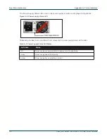
Figure 4-1
displays an AC power supply, including the power socket on the left side of the module.
Figure 4-1: AC Power Supply
The accessory kit provides two IEC-320 C13 to C14 power cables, each two meters long for 500W/
750W/ 1100W power supplies. Systems with 1900W power supplies come with C19 to C20 power
cables.
4.1.2
DC Power Supplies
The following two power supplies are supported.
•
PWR-1900DC
•
PWR-500DC
Figure 4-2: Supported DC power supplies
Important!
A disconnect device must be provided as part of the installation .
Un dispositif de sectionnement doit être fourni dans le cadre de l'installation.
• PWR-500AC
• PWR-1900AC
• PWR-745AC
• PWR-1100AC
Summary of Contents for DCS-7050SX-128
Page 38: ...36 Quick Start Guide 7000 Series 2 RU Data Center Switches Appendix C Front Panel ...
Page 40: ...38 Quick Start Guide 7000 Series 2 RU Data Center Switches Appendix D Rear Panel ...
Page 44: ...42 Quick Start Guide 7000 Series 2 RU Data Center Switches Appendix F Taiwan RoHS Information ...


