background image

Front Panel

8.3

 Operating Mode Button

This section describes the functionality of the mode button located on the front panel of the switch.

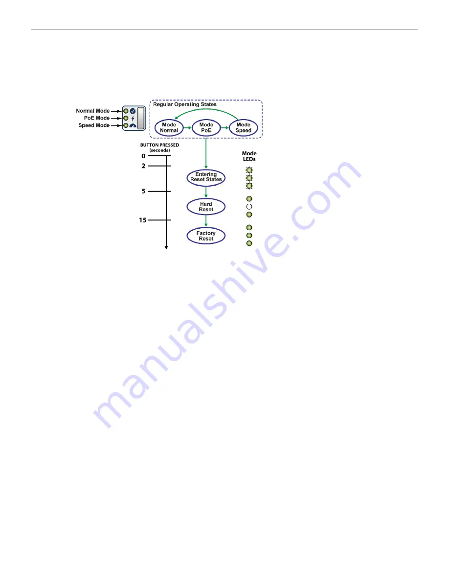
Figure 16: Mode Button States

The mode button port LEDs will transition to different modes as listed below when the user presses
the mode button for less than 2 seconds and the same is indicated by the corresponding mode status
LED.

Normal Mode

PoE Mode

Speed Mode

In addition to controlling the port/mode LEDs, the button can trigger other actions including a hard
reset and a factory reset. To access these actions, it is required to long-press the button as shown in
the figure 

Figure 16: Mode Button States

.

Entering Reset States:

If you press-and-hold the button for more than 2 seconds, all the 3 mode status LEDs will flash to
indicate the transition from regular operating states to reset states. If the button is released before
5 seconds, no action will occur and the system will return to its previous mode (normal, PoE, or link
speed).

Hard Reset:

If you press-and-hold the button for about 5 to 15 seconds, it will trigger a hard reset of the system
2 seconds later.

Factory Reset:

If you press-and-hold the button for about 15 seconds or longer, it will trigger a hard reset of
the system 2 seconds later. In addition, the system will also trigger factory reset on system
configuration.

31

Summary of Contents for CCS-710P-12

Page 1: ...Quick Start Guide Ethernet Switch CCS 710P 12 CCS 710P 16P Arista Networks www arista com DOC 05297 01 ...

Page 2: ...operty of Arista Networks in the United States and other countries Use of the Marks are subject to Arista Network s Term of Use Policy available at www arista com en terms of use Use of marks belonging to other parties is for informational purposes only Headquarters 5453 Great America Parkway Santa Clara CA 95054 USA 1 408 547 5500 www arista com Support 1 408547 5502 1 866 476 0000 support arista...

Page 3: ...7 4 1 Wall Mount 7 4 1 1 L Bracket Wall Mount Default 7 4 1 2 3 in 1 Bracket Wall Mount Optional 8 4 2 Under Table Mount 11 4 2 1 L Bracket Under Table Mount Default 11 4 2 2 3 in 1 Bracket Under Table Mount Optional 12 4 3 Desktop Mount Default 14 4 4 Magnetic Mount Optional 15 4 5 DIN Rail Mount Optional 16 4 6 1RU Rack Mount Optional 18 4 6 1 Attaching Mounting Brackets to the Chassis 18 4 6 2 ...

Page 4: ...Chapter 9 Rear Panel 33 Chapter 10 Regulatory Model Numbers 35 Appendix A Screw Size Details 37 Appendix B Class A EMC Statement 39 Appendix C China RoHS 41 Appendix D BSMI RoHS 43 iv ...

Page 5: ... Note Only qualified personnel should install service or replace this equipment Seul le personnel qualifié doit installer service ou remplacer cet équipement 1 3 Receiving and Inspecting the Equipment Upon receiving the switch inspect the shipping boxes and record any external damage Retain packing materials if you suspect that part of the shipment is damaged the carrier may need to inspect them I...

Page 6: ...n technical support in any of the following ways Email support arista com This is the easiest way to create a new service request Include a detailed description of the problem and the output of show tech support Web https www arista com en support A support case may be created through the support portal on our website You may also download the most current software and documentation as well as vie...

Page 7: ...cifications Operational and Storage Operating Temperature Switch Desktop Hanging Under Table Storage Temperature Operating Altitude Relative Humidity CCS 710P 12 AN1758 0 to 40 C 32 to 104 F 0 to 35 C 32 to 95 F 0 to 3 000 meters 0 to 10 000 feet 0 to 3 000 meters 0 to 10 000 feet 95 CCS 710P 16P AN1786 0 to 40 C 32 to 104 F 0 to 35 C 32 to 95 F 0 to 3 000 meters 0 to 10 000 feet 0 to 3 000 meters...

Page 8: ...oE Power Budget Switch PSU Model PoE Power Budget CCS 710P 12 AN1758 PWR 150 ADP 110W CCS 710P 12 AN1758 PWR 280 ADP 240W CCS 710P 16P AN1786 90W PoE PD 40W CCS 710P 16P AN1786 PWR 150 ADP 100W CCS 710P 16P AN1786 PWR 280 ADP 230W 4 ...

Page 9: ...ad the switch at the bottom if it is the only item in the rack Power Requirements Power requirements vary by switch and power supply model Refer to Table 3 Switch Specifications Power Ratings and for information regarding your specific system Note The power input plug socket combination must be accessible at all times it provides the primary method of disconnecting power from the system Other Requ...

Page 10: ...ea Use a conductive work surface such as an anti static mat to dissipate static charge Wear a conductive wrist strap to dissipate static charge accumulation Minimize handling of assemblies and components Keep replacement parts in their original static free packaging Remove all plastic foam vinyl paper and other static generating materials from the work area Use tools that do not create ESD 6 ...

Page 11: ...n 1 Bracket Under Table Mount Optional Desktop Mount Default Magnetic Mount Optional DIN Rail Mount Optional 1RU Rack Mount Optional Attaching Mounting Brackets to the Chassis Inserting the Switch into the Rack 4 1 Wall Mount This section provides instructions for wall mounting the switch 4 1 1 L Bracket Wall Mount Default This section provides instructions for wall mounting the switch using L Bra...

Page 12: ... the mounting position to attach the switch to the wall 4 Drill four holes two on each side 7x25mm deep on the wall Refer to the L Bracket for detailed hole locations 5 Insert M4 screw anchor to the four holes drilled on the wall 6 Place the chassis attached with L Bracket on the wall aligning with the mounting holes and secure the device with M4x25mm screws 7 Tighten the screws to fix the device ...

Page 13: ...1 Determine the wall mounting position to attach the device 2 Place the 3 in 1 bracket on the wall and mark the mounting holes on the four corners aligning with holes on the 3 in 1 mounting bracket Figure 2 Attaching 3 in 1 Bracket to the Wall 3 Fix the 3 in 1 bracket to the wall using the screws 4 Attach the switch to the 3 in 1 bracket using the screws and studs Figure 3 Wall Mounting the Switch...

Page 14: ...U and fix with cable ties around it 1 PSU adapter bracket 2 Cable ties 8 Determine the wall mounting position to attach the PSU adapter bracket 9 Place the PSU adapter bracket on the wall and mark the mounting holes on the four corners aligning with the mounting bracket 1 Screw anchor M4 2 Screw M4x25mm 3 Flat surface wall 10 Fix the PSU adapter bracket to the wall using the screws 10 ...

Page 15: ...e_27 unique_27_Connect_42_section_b1r_xt1_yqb Note Ensure that the flat wooden table surface has a minimum thickness of 25mm for under table mounting 1 Position the L Bracket aligning with the chassis holes on the side of the switch and fix it with M4x6mm flat head screws The L Bracket is attached to the chassis 2 Attach the remaining L Bracket on the other side of the chassis and fix it with M4x6...

Page 16: ...l This section provides instructions for mounting the switch under the table desk using 3 in 1 mounting bracket Figure 5 Attaching 3 in 1 Bracket under the Table 1 Flat wooden table 2 Screw hole 3 Screw anchor M4 4 3 in 1 bracket 5 Screw M4x25mm 12 ...

Page 17: ...ss of 25mm for under table mounting 1 Determine the mounting position to attach the switch under the table 2 Place the 3 in 1 bracket under the table and mark the mounting holes on the four corners aligning with holes on the 3 in 1 mounting bracket Figure 5 Attaching 3 in 1 Bracket under the Table 3 Fix the 3 in 1 bracket under the table using the M4x25mm screws on the four corners 4 Attach the sw...

Page 18: ...ice is not stacked and avoid placing anything on the top cover of the device 1 Peel the four rubber feet from the master sheet provided in the kit 2 Attach the adhesive rubber feet to the four corners on the bottom of the switch The rubber foot prevents the switch from sliding from the table and to protect the table surface 3 Place the switch on the desktop or any flat surface with a connecting po...

Page 19: ...size refer to unique_27 unique_27_Connect_42_section_b1r_xt1_yqb Note While magnetic mounting the switch ensure that the front panel is facing sidewards or downwards Do not mount the switch with front panel facing up 1 Attach the switch to the 3 in 1 bracket using the screws provided in the magnetic mount kit 2 Tighten the screws to fix the device firmly 3 Attach the rubber magnet to the 3 in 1 br...

Page 20: ...ead screw M4x6mm 5 DIN rail Note For more information regarding the screw size refer to unique_27 unique_27_Connect_42_section_b1r_xt1_yqb 1 Position the DIN mount bracket on the chassis aligning with the holes and fix it with M4x6mm flat head screws The DIN mount bracket is attached to the chassis 2 Place the DIN rail on the DIN mount bracket by aligning with the DIN rail holder 16 ...

Page 21: ...N rail hook as shown in the below image 1 DIN mount bracket 2 DIN rail hook 3 DIN rail holder 4 Press the DIN rail holder firmly and rotate the chassis to fit in the device 5 Place the PSU adapter bracket on the PSU and fix with cable ties around it 1 PSU adapter bracket 2 Cable ties 17 ...

Page 22: ... ties 5 PSU rubber pads 4 6 1RU Rack Mount Optional This section provides instructions for rack mounting the switch To mount the switch in a rack you need to assemble the mounting brackets to the chassis and then attach the brackets to the rack posts 4 6 1 Attaching Mounting Brackets to the Chassis This section describes the steps to attach mounting brackets to the switch chassis Figure 10 Attachi...

Page 23: ...steps to attach the switch into the rack Figure 11 Inserting the Switch into the Rack 1 Thread screw M4x6mm Note For more information regarding the screw size refer to unique_27 unique_27_Connect_42_section_b1r_xt1_yqb 1 Place the switch into the rack by aligning the holes of the mounting bracket with the appropriate holes on the chassis 2 Secure the switch into the rack using the thread screws pr...

Page 24: ...image 1 Cable ring 2 Cable ties 5 Position the rack against the rack posts and mount the rack to the equipment rack 1 Screw M4x8mm 2 Rack posts 6 Secure the equipment rack using the screws 7 For thermal purposes make sure that there is 1RU clearance above the rack mount bracket 20 ...

Page 25: ... and national installation requirements Note The earth connection must not be removed unless all supply connections are disconnected 1 Ensure the rack is properly grounded and is in compliance with ETSI ETS 300 253 2 Verify that there is a good electrical connection to the grounding point on the rack no paint or isolating surface treatment 3 Attach the solder terminal lug not provided with the swi...

Page 26: ...22 ...

Page 27: ...een The system is operating in a normal initialization sequence Normal operations Blue The locator function is active System Status LED Amber System is malfunctioning System is overheating or temperature sensors have recorded passing the SW defined critical threshold The switch will automatically execute a graceful shutdown shortly Off Not connected to the cloud Green System is connected to the cl...

Page 28: ...mode is not selected Port PoE Mode LED Green Port LED is selected to indicate port PoE status Off Speed mode is not selected Port Speed Mode LED Green Port LED is selected to indicate port speed Table 6 Port LED Modes Port LEDs Normal Mode PoE Mode Speed Mode Off Port link is down Off No PoE Blinking Amber 10M Green Port link is up Blinking Amber 15W Amber 100M 1GE RJ45 Port LED P1 to P12 Amber Po...

Page 29: ...abled Off No PoE Green 5G Off Port link is down Off No PoE Blinking Amber 1G Green Port link is up Blinking Green 60W Amber 2 5G 5GE RJ45 Port LED P16 710P 16P only Amber Port is software disabled Green 90W Green 5G Off Port link is down Blinking Amber 100M Green Port link is up Amber 1G SFP Port LED P13 to P14 710P 12 P17 to P18 710P 16P Amber Port is software disabled Off No PoE Green 10G 25 ...

Page 30: ...26 ...

Page 31: ...ng the sales team DIN rail mount kit DIN mount bracket and power adapter bracket 1RU rack mount kit Rack mount bracket Magnet mount kit 3 in 1 bracket rubber magnet and power adapter bracket SKU and Product Details The following are the list of SKU numbers related to the respective product Table 7 SKU and Product Details SKU Product Description PWR 150 ADP Arista Power Adapter 150W PoE AC Spare PW...

Page 32: ...28 ...

Page 33: ...P 12 Front Panel CCS 710P 16P Front Panel Operating Mode Button 8 1 CCS 710P 12 Front Panel The CCS 710P 12 front panel includes the following key components Figure 14 CCS 710P 12 Front View 1 System status LEDs 2 1GE RJ45 port LEDs 3 SFP ports 4 SFP port LEDs 5 Gigabit Ethernet RJ45 ports with 30W PSE 6 USB port 7 Console port 8 Mode button 9 Mode status LEDs 29 ...

Page 34: ... 1 System status LEDs 2 1GE RJ45 port LEDs 3 5GE port LEDs 4 SFP ports 5 SFP port LEDs 6 6A Uplink 5 Gigabit Ethernet RJ45 port with 90W PD 6B Uplink 5 Gigabit Ethernet RJ45 port 6C 5 Gigabit Ethernet RJ45 ports with 60W PSE 7 Gigabit Ethernet RJ45 ports with 30W PSE 8 USB port 9 Console port 10 Mode button 11 Mode status LEDs 30 ...

Page 35: ...required to long press the button as shown in the figure Figure 16 Mode Button States Entering Reset States If you press and hold the button for more than 2 seconds all the 3 mode status LEDs will flash to indicate the transition from regular operating states to reset states If the button is released before 5 seconds no action will occur and the system will return to its previous mode normal PoE o...

Page 36: ...32 ...

Page 37: ...ribes the rear panel of the Ethernet Switch CCS 710P 12 and CCS 710P 16P The rear panel includes the following key components Figure 17 CCS 710P 12 and CCS 710P 16P Rear View 1 Earth grounding point 2 Kensington lock hole 3 Power supply 33 ...

Page 38: ...34 ...

Page 39: ...his section lists the regulatory model numbers RMNs of the ethernet switch described in this document Table 8 Regulatory Model Numbers and Product Numbers Regulatory Model Number RMN Product Number AN1758 CCS 710P 12 AN1786 CCS 710P 16P 35 ...

Page 40: ...36 ...

Page 41: ...Appendix A Screw Size Details Refer to the following template for detailed screw size information 37 ...

Page 42: ...38 ...

Page 43: ...Appendix B Class A EMC Statement Refer to the following section for detailed Class A EMC Statement Figure 18 Traditional Chinese Class A EMC Statement Taiwan 39 ...

Page 44: ...40 ...

Page 45: ...Appendix C China RoHS This appendix provides RoHS information for ethernet switch covered by this guide Figure 19 China RoHS 41 ...

Page 46: ...42 ...

Page 47: ...Appendix D BSMI RoHS This appendix provides RoHS information for ethernet switch covered by this guide Figure 20 BSMI RoHS 43 ...

Page 48: ...44 ...

Reviews: