2
Screw M4x25mm
3
Flat head screw M4x6mm
4
Screw anchor M4
5
Flat surface wall
Note: For more information regarding the screw size, refer to
unique_27_Connect_42_section_b1r_xt1_yqb
1. Position the L-Bracket aligning with the chassis holes on the side of the switch and fix it with
M4x6mm flat head screws. The L-Bracket is attached to the chassis.
2. Attach the remaining L-Bracket on the other side of the chassis and fix it with M4x6mm flat head
screws.
3. Determine the mounting position to attach the switch to the wall.
4. Drill four holes (two on each side) 7x25mm deep on the wall. Refer to the L-Bracket for detailed
hole locations.
5. Insert M4 screw anchor to the four holes drilled on the wall.
6. Place the chassis, attached with L-Bracket, on the wall aligning with the mounting holes and secure
the device with M4x25mm screws.
7. Tighten the screws to fix the device firmly to the wall.
4.1.2
3-in-1 Bracket Wall Mount (Optional)
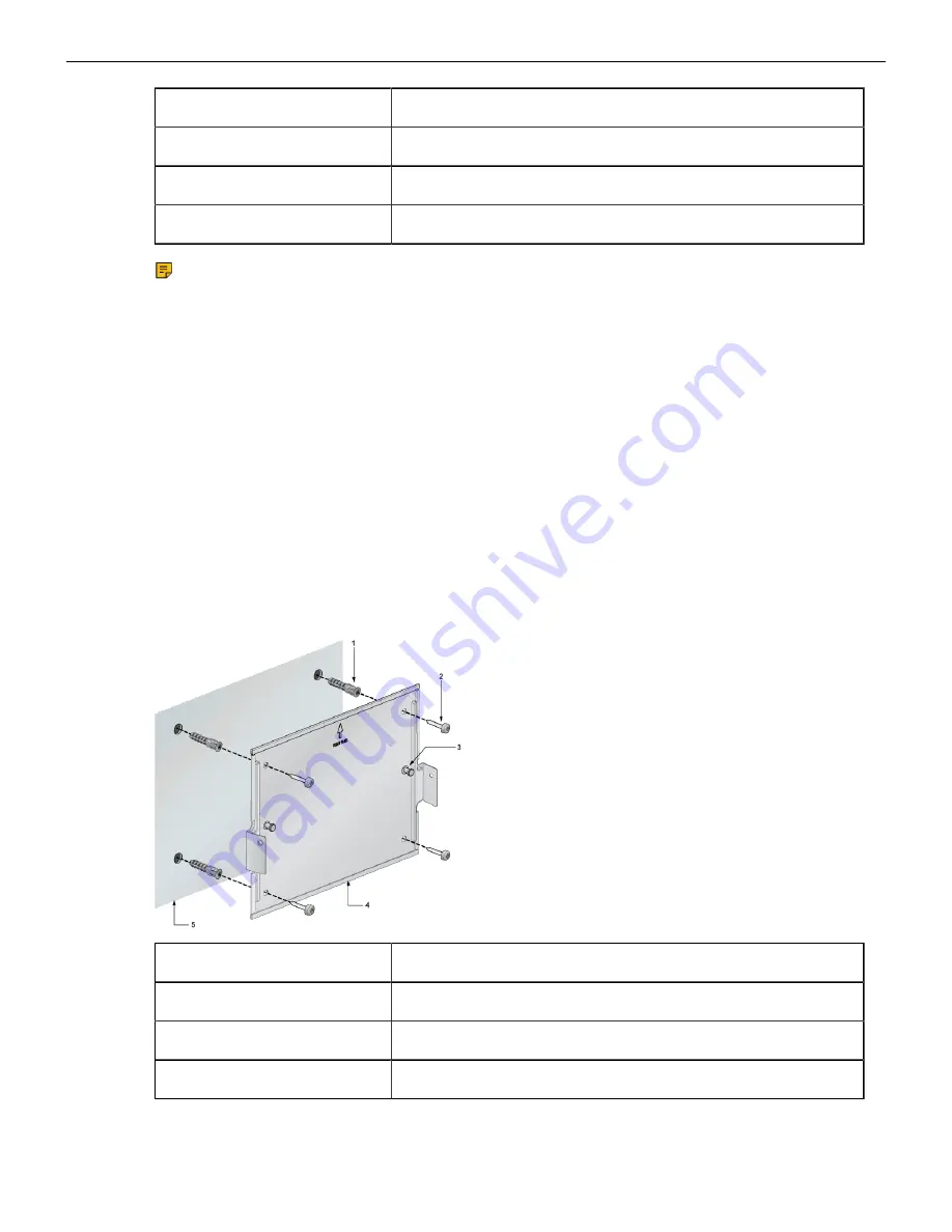
This section provides instructions for wall mounting the switch using a 3-in-1 mounting bracket.
Figure 2: Attaching 3-in-1 Bracket to the Wall
1
Screw anchor M4
2
Screw M4x25mm
3
Cross hole stud
4
3-in-1 bracket
8


