background image

GB - 19

CHECK CLUTCH OPERATION

Auger and impeller must stop within 5 
seconds when attachment clutch/impeller 
brake lever is released.
Wheels must stop quickly when traction drive 
clutch lever is released.

If clutches do not engage or disengage 
properly, adjust or repair before operation 
(see 

Attachment Clutch/Brake Adjustment

 on 

page 25 and 

Traction Drive Clutch 

Adjustment

 on page 27).

CHECK CLUTCH SPRING 
ADJUSTMENT

Make sure the attachment clutch and traction 
drive clutch are adjusted to the range 
specified in 

Attachment Clutch/Brake 

Adjustment

 on page 25 and 

Traction Drive 

Clutch Adjustment

 on page 27.

CHECK TIRE PRESSURE

Keep tires at pressure listed on the tire 
sidewall. (see 

Check Tire Pressure 

on 

page 11).

CHECK AUGER GEARCASE 

IMPORTANT: 

Proper oil level must be 

maintained.

Gear cases are filled to the correct level at 
the factory. Unless there is evidence of 
leakage, no additional lubricant should be 
required. Check oil level each season or 
every 25 hours of operation.

To ensure adequate lubricant level:

1. Remove filler plug (Figure 16). Lubricant 

must be at least up to bottom of lubricant 
filler hole with unit resting on a level 
surface.

2. Add lubricant if required. Allow oil to 

drain to level of plug and replace plug. 

IMPORTANT: 

Use only Ariens special gear 

lubricant L-2 (Part Number 00008000). 
Gearcase filler plug may require an 
application of Loctite® 565 thread sealant 
with repeated servicing.

GENERAL LUBRICATION

Figure 17

IMPORTANT: 

Wipe each fitting clean before 

and after lubrication. Do not wipe gearcase 
filler plug; wiping the gearcase filler plug may 
remove thread sealant and cause leaks.

IMPORTANT: 

DO NOT allow grease or oil to 

get on friction disc, friction plate or belts.

NOTE: 

Apply Ariens Hi-Temp Grease or 

equivalent to the lubrication fittings. See 

SERVICE PARTS

 on page 31

.

Sno-Thro should be lubricated (Figure 17) at 
beginning of season or every 25 operating 
hours.

Auger Shaft

NOTE: 

To grease auger shaft, remove shear 

bolt nuts, and shear bolts. Apply grease at the 
grease zerks and then turn the auger 
assemblies on the auger shaft. Replace 
shear bolts per instructions in 

Shear Bolts

 on 

page 21.

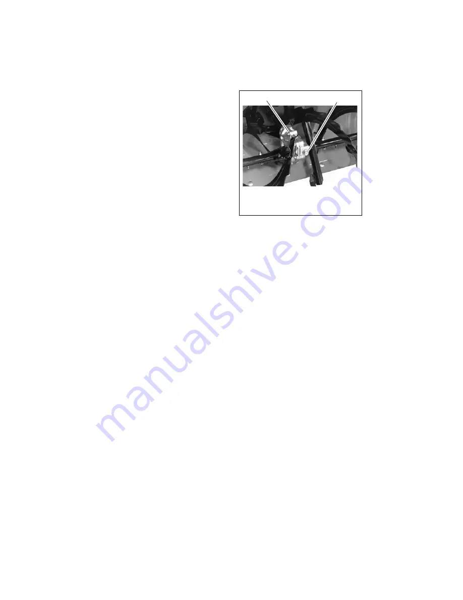
Figure 16

1. Auger Gearcase
2. Filler Plug

OS2600

1

2

Summary of Contents for 916003

Page 1: ...Owner Operator Manual Manuel Du Propriétaire Utilisateur Model 916003 AMP 24 03982600C 6 10 Printed in USA ENGLISH FRANÇAIS AMP 24 ...

Page 2: ... votre revendeur Rendez vous chez votre revendeur ou allez sur le site www ariens com pour consulter la liste des langues disponibles pour votre équipement Les manuels imprimés dans des langues différentes de l anglais sont également disponibles en téléchargement gratuit sur notre site Web http www ariens com MANUAL Before operation of unit carefully and completely read your manual If used imprope...

Page 3: ...et DISCLAIMER Ariens reserves the right to discontinue make changes to and add improvements upon its products at any time without public notice or obligation The descriptions and specifications contained in this manual were in effect at printing Equipment described within this manual may be optional Some illustrations may not be applicable to your unit DELIVERY Customer Note If you have purchased ...

Page 4: ...e and proper operation If unit is to be used by someone other than original purchaser loaned rented or sold ALWAYS provide this manual and any needed safety training before operation SAFETY DECALS AND LOCATIONS ALWAYS replace missing or damaged Safety Decals Refer to figure below for Safety Decal locations 1 WARNING SAFETY WARNING To avoid injury to hands and feet always disengage clutches stop dr...

Page 5: ... debris Thrown objects can cause injury Check for weak spots on docks ramps or floors Avoid uneven work areas and rough terrain Stay alert for hidden hazards Keep people away from unit while operating Keep children out of work area and under watchful care of a responsible adult Never direct discharge towards persons or property that may be injured or damaged by thrown objects Stop drive motor remo...

Page 6: ...se injury and property damage Always stand clear of the discharge area when operating this unit ALWAYS disengage attachment stop unit allow moving parts to stop and remove key before leaving operator s position ROTATING IMPELLER CAN CAUSE SERIOUS INJURY NEVER ATTEMPT TO UNCLOG OR CLEAN UNIT WHILE AUGER IS RUNNING Read understand and follow all instructions in the manual and on the machine before s...

Page 7: ...frequently If worn or damaged replace with manufacturer s recommended parts Keep all hardware properly tightened Check shear bolts frequently Maintain or replace safety and instruction labels as necessary For extended storage clean unit thoroughly Use only attachments or accessories designed for your unit Do NOT put batteries in fire or mutilate Explosive Gases NO flames NO sparks NO smoking near ...

Page 8: ...le spring hooks when rotating handlebars upward 5 Install and tighten the hardware on the handlebar assembly 6 Tighten the hardware on the shift rod Make sure that the rod is correctly seated before tightening ASSEMBLY WARNING AVOID INJURY Read and understand the entire Safety section before proceeding WARNING Dropping or tipping over boxed unit could result in personal injury or damage to unit Fi...

Page 9: ...nnectors are fully seated and lock in place 5 Install battery cover To prevent damage to cover do not overtighten hex socket head screws IMPORTANT Both batteries must be disconnected to fully remove power from the electrical system IMPORTANT Battery cover also acts as the hold down for the batteries DO NOT operate unit without the cover securely installed with all hardware Install Discharge Chute ...

Page 10: ... to the dash 6 Position rubber seal cap over the top of snap fitting 7 Move deflector control lever to forward most position 8 Attach cable eye to pin on bottom of deflector control lever NOTE Hold down chute deflector cap if needed for more cable slack 9 Secure cable eye to control lever with washer and hairpin 10 Test controls to be sure deflector works properly NOTE If deflector does not follow...

Page 11: ... Controls Ensure unit runs and performs properly Refer to Operation Run in Attachment Belt 1 Run unit according to Starting and Shut Off on page 17 2 Engage attachment clutch lever and run attachment for about 15 minutes 3 Stop unit wait for all moving parts to stop and remove key 4 Adjust clutch idler according to Attachment Clutch Brake Adjustment on page 25 1 Upper Mounting Hole 2 Snap Fitting ...

Page 12: ... Chute Deflector 7 Discharge Chute 8 Impeller 9 Auger 10 Scraper Blade 11 Auger Gearcase 12 Clean out Tool 13 Axle Lock Pin 14 Skid Shoe s 15 Belt Cover 16 Battery Cover 17 Charging Port 18 Key Power Switch 19 Battery Level Indicator 20 PTO Switch CONTROLS AND FEATURES Figure 10 1 2 4 5 6 7 8 9 10 11 12 13 14 20 19 18 15 16 17 3 ...

Page 13: ...iately release the attachment clutch lever and move the unit into a heated area to thaw NOTE If belt squeals when impeller turns freely see Attachment Drive Belt Replacement on page 23 Power Switch Operate power switch with a removable key Power switch has two positions ON 1 and OFF 2 Always remove key when unit is unattended or connected to battery charger Battery Level Indicator When the power s...

Page 14: ...o throw snow lower Place deflector remote in a rearward notch to throw snow higher Discharge Chute Discharge chute rotates 200 ALWAYS position discharge chute in safe direction and angle away from operator and bystanders before engaging auger Discharge Chute Crank IMPORTANT If chute does not stay in set position adjust as directed in SERVICE AND ADJUSTMENTS on page 20 or repair before operation Ro...

Page 15: ...cessary If a charge is required the battery charger sends a minimal level of current Over time this low rate of charge helps to extend battery life by equalizing charge imbalances between cells This low charge rate also prevents damage to the batteries from the forming of lead sulfate which occurs when batteries remain in a discharged state If there is a power outage while the battery charger is c...

Page 16: ...approximately 3 hours see ACCESSORIES on page 31 6 To use Sno Thro disconnect battery charger from wall outlet and disconnect from unit charging port Store charger in a dry area away from children pets heat and moisture 1 Check Function of Clutches If clutches do not engage or disengage properly adjust or repair before operation See Attachment Clutch Brake Adjustment on page 25 and Traction Drive ...

Page 17: ...ing parts to come to a complete stop 4 Disengage PTO switch Drive motor will stop 5 Turn power switch to OFF position and remove key 6 Attach unit to battery charger NOTE Try out each control without the drive motor running to see how it works and what it does SNOW REMOVAL NOTE Attachment clutch should be engaged before wheel drive clutch when throwing snow 1 Select speed control position and dire...

Page 18: ...requent service may be required Batteries MUST be connected to battery charger after every use regardless of length of time unit was operated After batteries are charged the battery charger must remain connected until the next use Failure to keep batteries fully charged will reduce battery life and void battery warranty CHECK DUAL HANDLE INTERLOCK Check operation of dual handle interlock See Dual ...

Page 19: ...sure adequate lubricant level 1 Remove filler plug Figure 16 Lubricant must be at least up to bottom of lubricant filler hole with unit resting on a level surface 2 Add lubricant if required Allow oil to drain to level of plug and replace plug IMPORTANT Use only Ariens special gear lubricant L 2 Part Number 00008000 Gearcase filler plug may require an application of Loctite 565 thread sealant with...

Page 20: ...kid shoes should be adjusted as conditions require Figure 18 1 Position unit on a hard flat smooth level surface 2 Adjust skid shoes by inserting a spacer of desired thickness under center of scraper blade 3 Loosen skid shoe hardware 4 Slide skid shoe to flat surface Allow 1 8 in 3 mm between scraper blade and hard smooth surfaces Allow 1 1 4 in 30 mm between scraper blade and uneven or gravel sur...

Page 21: ...SCHARGE DEFLECTOR CONTROL ADJUSTMENT Figure 20 If discharge deflector does not follow full range of travel 1 Push deflector remote all the way forward 2 Loosen adjusting nuts on remote deflector cable attached to the chute deflector Figure 20 3 To adjust the deflector lower Loosen bottom adjustment nut and tighten top adjustment nut To adjust deflector higher Loosen top adjustment nut and tighten ...

Page 22: ... pivot pin along the shift rod until it aligns with the mating hole on the speed selector arm and then turn it up the shift rod 3 turns Insert the pivot pin into hole 5 Connect the pivot pin to the speed selector arm with the hardware removed in step 1 6 Check forward and reverse speeds a Move power and PTO switches to the ON position b Shift speed selector into the first forward speed c Engage th...

Page 23: ...t handlebars firmly or tip unit up on housing and remove bottom cover by removing six cap screws before separating unit 9 Support Sno Thro frame and housing 10 Remove hex bolts securing housing to frame two on each side Tip housing and frame apart on pivot pin See Figure 25 11 Remove attachment drive belt from attachment pulley hold brake away from belt Figure 23 1 Shift Rod 2 Adjustment Pivot Pin...

Page 24: ...s 3 Place the unit into the service position on a level surface see Service Position on page 18 4 Remove the bottom cover by removing six cap screws NOTE To gain belt clearance remove swing gate spacer Figure 27 so drive plate can be slid over until finger is out of frame and drive plate can swing past stop hole in frame See Figure 28 WARNING AVOID INJURY Auger must stop within 5 seconds when atta...

Page 25: ...om unit 1 Remove the belt cover 2 Loosen jam nut 3 on cable adjustment barrel 2 and then turn the adjustment barrel down to shorten cable and remove all cable slack See Figure 29 3 With the attachment clutch disengaged check that the attachment idler arm lightly touches the frame See Figure 30 4 Tighten jam nut on cable adjustment barrel Figure 27 OS2630 1 Swing Gate Spacer 2 Drive Plate 1 2 Figur...

Page 26: ...n adjustment nut and recheck roller clearance Adjust the Attachment Clutch Cable Spring Extension 1 Check the attachment clutch cable spring extension Measure the length of the attachment clutch cable spring with the clutch lever disengaged Then measure the attachment clutch spring with the clutch lever engaged See Figure 32 The spring should be 1 2 9 16 in 12 7 14 3 mm longer when the clutch leve...

Page 27: ...ithin specified ranges IMPORTANT If adjustments cannot be brought into specified ranges see your Dealer for repairs TRACTION DRIVE CLUTCH ADJUSTMENT If drive slips adjust traction clutch to compensate for friction disc wear To test traction clutch Figure 34 1 Put unit in first forward speed 2 With power switch off push unit forward while slowly moving the traction drive clutch lever toward the han...

Page 28: ... carrier bearing 12 Remove old friction disc Put the new friction disc in place cup side to carrier bearing 13 Reinstall three screws into new friction disc and carrier bearing Torque to 5 6 lbf ft 6 8 8 13 N m 14 Insert new friction disc assembly into frame Install washers onto carrier bearing and slide into speed selector arm 15 Slide hex shaft through new friction plate assembly Install pinion ...

Page 29: ... understand the entire Safety section before proceeding TROUBLESHOOTING PROBLEM PROBABLE CAUSE CORRECTION Drive motor will not run 1 PTO switch in ON position when key turned ON 1 Turn PTO switch OFF before turning key switch ON 2 Traction or attachment clutch levers engaged 2 Release levers 3 Discharged batteries 3 Charge batteries see Charging the Batteries on page 15 4 Disconnected batteries 4 ...

Page 30: ...flashing red light under the cover 1 A trouble code has been set in the electrical system ____ long flash short flash Code Perform the suggested correction If trouble code resumes contact your Ariens Dealer 1 ____ ____ Motor Coil Overheated 1 Turn key to OFF position allow unit to fully cool before resuming 2 ____ ____ Motor Position Error 2 Contact your Ariens Dealer 3 ____ ____ Controller Overhe...

Page 31: ...LED on battery charger does not light after 7 hours 1 Battery charger connector not seated in charging port 1 Insert battery charger connector completely into charging port 2 Faulty battery or batteries 2 Replace defective battery or batteries see Removing and Installing Batteries on page 22 Green READY LED on battery charger flashes 1 Faulty battery or batteries 1 Replace defective battery or bat...

Page 32: ...tor Control Remote Auger Snow Clearing Width in cm 24 0 61 0 Gear Case Aluminum Auger Diameter in cm 11 0 27 9 Housing Height in cm 17 5 44 5 Impeller Impeller Diameter in cm 12 0 30 5 Impeller Speed No Load RPM 1330 Drive Blower Drive HA Belt Drive System Disc O Matic Speeds 6 Forward and 2 Reverse Axle Control Pin Lock Pneumatic Tires in 13 x 4 6 Size and Weight Length in cm 53 134 6 Height in c...

Page 33: ...y packs or battery subassemblies that fail due to accident neglect abuse improper maintenance improper storage or improper charging procedures Service Parts and Accessories Warranty Genuine Ariens or Gravely brand service parts and accessories are warranted to be free from defects in material and workmanship for a period of 90 days after the date of purchase An authorized Ariens dealer will repair...

Page 34: ...m time to time change the design of its products Nothing contained in this warranty shall be construed as obligating Ariens to incorporate such design changes into previously manufactured products nor shall such changes be construed as an admission that previous designs were defective LIMITATION OF REMEDY AND DAMAGES Ariens Company s liability under this warranty and under any implied warranty tha...

Page 35: ......

Page 36: ...Ariens Company 655 West Ryan Street Brillion WI 54110 1072 920 756 2141 Fax 920 756 2407 www ariens com www ampbyariens com ...

Reviews: