


030-713-C0 Rev A WC
Page 10 of 23
5 Installation
This chapter is provided for qualified personnel to install the product, which shall be mounted in a clean and dry
environment.
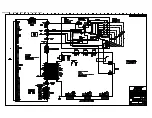
NOTE: To aid the user with installation, frequent reference is made to drawings located at the rear of the manual.
5.1 Safety
Precautions
WARNING
Hazardous voltages are present at the input of power systems. The DC output from the rectifiers
and battery system has a high short circuit current capacity that may cause severe burns and
electrical arcing.
Before working with any live battery or power system/distribution center, follow these precautions:
•
Remove all metallic jewelry; e.g., watches, rings, metal rimmed glasses, necklaces.
•
Wear safety glasses with side shields (and prescription lenses if necessary) at all times during installation.
Metallic tools must be insulated.
The installer should follow all applicable local rules and regulations for electrical and battery installations; e.g.,
CSA, UL, CEC, NEC, OSHA, and local fire codes.
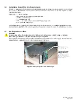
5.2 Shelf
Preparation/Mounting
The shelf has been designed for flush mounting in a standard EIA 19" relay rack. See drawing 030-713-06.
NOTE: The shelf shall be mounted in a clean and dry environment. Allow at least 1.75” of free space around the unit for
unrestricted convection cooling airflow.
Mounting brackets accommodate either 1” or 1-3/4” rack spacing. The shelf should be mounted to the rack using
at least two #12 – 24 x 1/2” screws in each bracket. Philips-type screws and screwdriver should be used to
eliminate the possibility of slippage and scratching of the unit’s exterior. Washers (such as internal tooth) or
special screws that are designed to cut through the painted surface should be used to ensure a good chassis
ground.
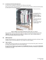
5.3 Module
Insertion/Removal
Insert by placing the module on the shelf bottom and sliding the module into the rear connectors (inside of the
shelf). Apply pressure on the handles to engage the rear connector in the shelf receptacle. Tighten the screw on
the bottom of the faceplate to secure the module to the shelf.
NOTE: Do not force a module into position if it does not seat properly. All modules are keyed to ensure that the correct
module type is used.
To remove modules, loosen the screw on the bottom of the faceplate. Grasp handle and pull out, sliding the
module away from the rear connectors and out of the shelf.
Summary of Contents for ALPHA OUTBACK ENERGY Cordex 48-1kW
Page 1: ...Cordex 48 1kW 19 Shelf Flush Mounting Up To 3000W With Distribution 030 713 B2 ...
Page 14: ...This page intentionally left blank ...
Page 38: ...03071305B__ sch 1 Mon May 14 15 17 29 2007 ...
Page 39: ...03071305B__ sch 2 Mon May 14 15 17 32 2007 ...