


030-713-C0 Rev A WC
Page 4 of 23
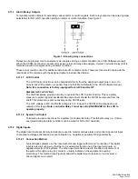
2.1.1.4
LED Activity During Software Upload
When a rectifier software upload is in progress, the LEDs will behave in a distinctly different way
to indicate new rectifier software is being transferred from the CXC.
When a rectifier data transfer is in progress, all three LEDs will flash in a sequence lasting 1.5
seconds. When the last LED is lit, the sequence is repeated beginning at the first LED.
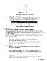
2.1.1.5
LED Activity During ‘Locate Module’ Command from CXC
When the ‘locate module’ command has been received from the CXC, the LEDs will behave in
another distinct fashion so that the rectifier is easier to visually identify among adjacent
rectifiers.
This state is entered when commanded via the CXC. The LEDs will flash in a ping-pong pattern
repeating every 2 seconds.
The ping-pong pattern lights each LED sequentially. After the last LED is lit, each LED is lit in
reverse sequence. When the first LED is lit, the pattern repeats. The effect makes it appear as if
the light is bouncing between the first and last LED.
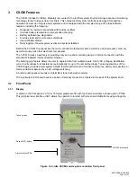
2.1.2 Mechanical
A thumbscrew is provided to secure the rectifier into the shelf. During normal operation the rectifier shall be
locked into position. A handle (or grip) is incorporated into the front panel to facilitate the removal of the rectifier
from the shelf. No special tools are required.
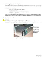
2.2 Rear
Panel
Located on the rear panel of the rectifier are connectors for shelf power and communications.
2.3
True Module Fail Alarm
The power modules have a “true” fail alarm. This provides a true indication of the power module’s ability to source
current. When the module’s output current drops below 2.5% of the rated output a low output current condition is
detected and the Module Fail detection circuit is activated. This circuit momentarily ramps up the output voltage to
determine if the module will source current. If no increase in current is detected, the Module Fail alarm is
activated. The module will test once every 60 seconds for the condition until current is detected. Output voltage
ramping will cease upon detection of current
. A minimum 2.5% load is required to avoid the Ramp Test Fail
alarm; this can typically be provided with the parallel system battery. Activation of this alarm could indicate a failed
module or a failed load.
NOTE: For Cordex rectifier systems without batteries (or with a very light load; below 2.5% of rated output) it is
recommended that the ramp test be disabled to avoid nuisance alarms. The Ramp Test feature is
enabled/disabled via the CXC menu item: Rectifiers, Configure Settings.
2.4 Heat
Dissipation
Heat dissipation is achieved through natural (bottom to top) convection cooling.
NOTE: Some rectifier shelves incorporate fan aided cooling to increase the temperature rating of the module. See shelf
manual supplied with your system.
2.5
Over Temperature Protection
Each module is protected in the event of an excessive increase in temperature due to component failure or
cooling airflow blockage. During over temperature conditions, the rectifier limits the output power as well as the
output current.
At 65ºC output power and current limit are reduced to 70%.
If temperature continues to
increase, a shutdown of the rectifier is initiated. The rectifier shall restart automatically if the temperature has
returned to a safe level.
1
A battery connected to the output of the rectifier will draw current when the voltage ramp occurs. Therefore the rectifier fail alarm will not be generated
with a battery connected.
Summary of Contents for ALPHA OUTBACK ENERGY Cordex 48-1kW
Page 1: ...Cordex 48 1kW 19 Shelf Flush Mounting Up To 3000W With Distribution 030 713 B2 ...
Page 14: ...This page intentionally left blank ...
Page 38: ...03071305B__ sch 1 Mon May 14 15 17 29 2007 ...
Page 39: ...03071305B__ sch 2 Mon May 14 15 17 32 2007 ...