background image

E T V I S I O N   M A N U A L  


19 


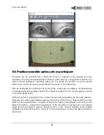
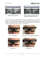
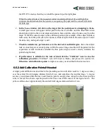
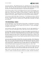
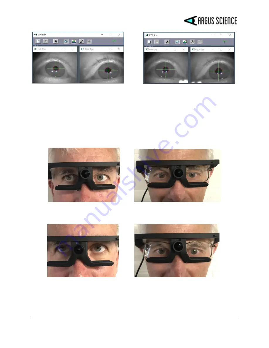
           subject not wearing eye glasses   


subject weraring eye glasses(note specular 

                                                                                              reflections near bottom inner corners) 


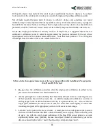
If  the 

ETVision

  frame  is not  positioned  correctly  on  the  face,  as  described  above,  select  a  different 

nosepiece  or  remove  the  nosepiece  altogether  to  position  the  frame  higher  or  lower  on  the  face  as 
necessary.   It is suggested that the participant completely remove the frame  before the nosepiece is 
swapped  or  removed.    The  photos,  below,  show  examples  of  positioning  that  is  correct  as  well  as 
examples of positioning that is either too high or too low on the face.  


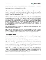
                   Correct optics position                        Correct optics position on subject with eye glasses 


                          Optics too low                                                    Optics too high 


Summary of Contents for ETVision

Page 1: ...ETVision InstructionManual MANUAL VERSION preliminary ver1 1 June 2019 techsupport argusscience com Web site www argusscience com...

Page 2: ...form Single Point Calibration 21 6 5 2 Add Calibration Points if Needed 22 6 6 Monitor gaze data and system status 25 6 6 1 Status Indicators 25 6 6 2 Left Eye and Right Eye windows 25 6 6 3 Scene Ima...

Page 3: ...Subject Calibration tab 55 8 4 4 System Configuration tab 56 8 4 5 About Tab 58 8 5 Appendix E Minimum specifications for ETVision PC and software installation instructions 59 8 5 1 PC specifications...

Page 4: ...arable cameras to compute point of gaze with respect to a scene camera coordinate frame The laptop can record the digital gaze coordinates 180 times per second This digital file also includes pupil di...

Page 5: ...eye ETVison uses non coherent illumination There are no lasers in the headgear 2 2 Safety Disclaimer Argus Science LLC has taken due care in preparing this manual and accompanying documentation inclu...

Page 6: ...it resembles an eyeglasses frame that can be worn by itself or over the participant s prescription eyeglasses It contains miniature eye cameras that view each eye and a scene camera that views the sce...

Page 7: ...st above the nosepiece Scene camera focus is adjusted by rotating the lens A microphone is located in the part of the frame that sits just above the participant s eyebrows An optional visor attaches a...

Page 8: ...le A set screw on the bottom of the Controller directly under the HDMI port is used to secure the HDMI cable connector after insertion The Controller can be connected to the ETVision Laptop using the...

Page 9: ...urs when the system is idle 3 3 ETVision PC ETVision systems usually include a laptop PC running Windows 10 ETV PC When supplied by Argus Science as part of the ETVision system the ETVison software ap...

Page 10: ...E T V I S I O N M A N U A L 10 4 Interconnections Basic ETVision System Interconnections headphones not normally supplied as part of ETV system...

Page 11: ...E T V I S I O N M A N U A L 11 ETVision connection to External Device Method 1 All other connection are as shown in the Basic System Interconnections diagram...

Page 12: ...E T V I S I O N M A N U A L 12 ETVision connection to External Device Method 2 All other connection are as shown in the Basic System Interconnections diagram...

Page 13: ...onnection between the Controller and the PC is detected the system will automatically connect via the cable If a cable connection is not detected the system will automatically connect via WiFi If the...

Page 14: ...t surface of the cornea Corneal Reflections or CRs to compute gaze within a scene Light from a pair of harmless near infra red LEDs on the head gear illuminate the eye area The near IR light is almost...

Page 15: ...nd the position of the optics with respect to the face vary somewhat from person to person gaze computation accuracy can be improved by incorporating data from calibration points points at which the p...

Page 16: ...ng When fully charged the LED will turn off This may take up to 4 5 hours if the battery was fully discharged Disconnect the power supply and proceed to the next section When the Controller is communi...

Page 17: ...LED turns red this means that the battery has less than 15 charge Either return the unit to idle and charge the battery as described in section 6 1 or plug in the power supply LED will turn yellow an...

Page 18: ...f the participant is wearing prescription eyeglasses the ETVision frame can simply be worn over the glasses as shown in one of the photos below When the subject is wearing the ETVision frame the top o...

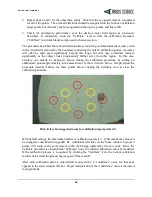
Page 19: ...r remove the nosepiece altogether to position the frame higher or lower on the face as necessary It is suggested that the participant completely remove the frame before the nosepiece is swapped or rem...

Page 20: ...he pupil and corneal reflections will be obscured during eye blinks The Scene window shows the image from the head mounted scene camera with a blue cross indicating the participant s point of gaze POG...

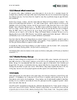
Page 21: ...ns do not need to be used for the current calibration 1 Have the participant hold their head still and look at a point near horizontal center and at or just below the vertical center of the scene came...

Page 22: ...nce over the desired visual field region Have the subject look at visual targets at several points within the scene image area that will important for the experiment or task and notice whether the blu...

Page 23: ...iew Yellow circles show approximate areas on the scene image within which additional 4 target points should usually be located 1 Do not close the calibration procedure after the single point calibrati...

Page 24: ...his case accuracy can usually be improved before closing the calibration procedure by adding an additional 4 points approximately in the areas shown by the red circles below Simply repeat the procedur...

Page 25: ...time on the Left Eye and Right Eye windows These windows are opened by default but can be closed and re opened by clicking the Eye icon on the menu bar Pupil recognition is indicated by a red ellipse...

Page 26: ...the scene camera graphically as a real time X Y plot point and also displays real time digital values for data computed by the system The POG Display area plots point of gaze as a moving spot on a di...

Page 27: ...just Gaze buttons at the lower left of the window are used for a manual gaze data offset feature that is explained in the next section If the manual offset function has not been enabled see next secti...

Page 28: ...on to Adjust feature turned off To disable the Drag Left Mouse Button to Adjust function turn the feature off and protect against accidentally creating offsets click the button to un depress it The Ma...

Page 29: ...d by the microphone will be recorded on scene video files data and video recording is described in the next section In order for audio from the PC microphone to be heard on headphones connected to the...

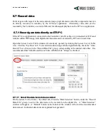
Page 30: ...on in real time Open the System Control Table window if not already opened by clicking the System Control Table icon Click the Eye Data tab To record video data along with the digital data file check...

Page 31: ...on subject calibration icon appears red opening a data file will automatically close the calibration mode Once the data file is opened the File button will change to a Close button and a button with...

Page 32: ...20x240 pixels and the scene image file resolution is 1280x720 pixels The update rate for both eye and scene files is 30 Hz Scene video files include audio tracks for the wearable optics microphone and...

Page 33: ...nd WiFi range of the ETV PC Data cannot however be simultaneously monitored or recorded by the ETVision PC application even if it is in range While SD card recording is in progress the ETVision applic...

Page 34: ...the Controller To use the default name or name most recently set in the Controller simply proceed to the next section To modify the profile name the Controller must be connected to the ETVision PC ap...

Page 35: ...ve data however the status indicators on the tool bar will continue to operate as long as the Controller is in range To stop recording press the record button again and hold for 1 second If the ETV PC...

Page 36: ...r dialog to select an emv file As previously mentioned it is suggested that this be an emv file that has been copied to a location on the PC hard drive rather than a file on the SD card First be sure...

Page 37: ...ze and pupil diameter data as well as the scene or eye video images A device connected to the LAN can send a channel of data to be recorded by ETServer along with gaze data and can remotely open and c...

Page 38: ...ight Eye Video Send Left Eye Video or Send Scene Video Digital data is always sent along with the video stream but only one of the video channels my be streamed The digital data items streamed will be...

Page 39: ...ication window type in the ETVision network name or IP address These can be found on the ETVision Network Configuration dialog as described in the previous section In the case of a direct connection f...

Page 40: ...tion dialog click Receive Data TCP or Receive Data UDP on the ETRemote application to begin receiving the video stream Select the Video tab on ETRemote to view the video data To send an external data...

Page 41: ...vice can connect to the ETVision if the device is connected to the same LAN The application must be able to open a socket connect to the Host IP address and port number and send receive data over this...

Page 42: ...es on CRs although the entire eye image will appear significantly darker and may be more difficult for the equipment operator to see when indoors Outdoors in bright daylight the eye images with lower...

Page 43: ...the participant is wearing prescription eyeglasses bright sunlight may create reflections on the eyeglass lenses that will interfere with the eye camera view This is especially likely to be a problem...

Page 44: ...boot process and battery has 15 charge Red Not connected Controller booted or in boot process and battery has 15 charge OFF Connected Controller in idle state not booted and Battery fully charged Whi...

Page 45: ...N M A N U A L 45 Record LED Color Condition OFF No SD card detected Green SD card detected and 90 full not currently recording Yellow SD card detected and 90 full not currently recording Red SD card...

Page 46: ...oints to be used in any order up to a maximum Total Calibration Points that is set on the System Control Table Subject Calibration tab dialog The highest Total Calibration Points number that can be se...

Page 47: ...stimate of POG based on data from the points so far entered Right clicking will undo the last point entered A confidence value which appears in the Scene Image window title bar after each calibration...

Page 48: ...lly ensure that the pupils and all CRs can be properly recognized at this point It is further recommended that additional points be added as described in section 6 5 since that sequence will most like...

Page 49: ...ace feature Data Item Type Size bytes Scale Factor Comment XDAT UInt16 2 1 Always available CU_video_field_num UInt16 2 1 Always available left_pupil_pos_horz UInt16 2 1 Always available right_pupil_p...

Page 50: ...ation_Y Int16 2 0 01 Available only if ET3S I enabled ET3S _right_eyelocation_Y Int16 2 0 01 Available only if ET3S enabled ET3S _left_eyelocation_Z Int16 2 0 01 Available only if ET3S enabled ET3S _r...

Page 51: ...converted to a float and multiplied by 0 01 the scale factor shown on the chart above This pixel value is the value displayed on the ETVision application on the Data Display window and the value show...

Page 52: ...nits of either inches or centimeters depending on the Position Units selected on the System Control Table System Configuration tab hdtrk X Y Z position values and azimuth elevation and roll orientatio...

Page 53: ...for use as the file name prefix on SD card recordings see section 6 7 2 1 The default profile name is ETDefault 8 4 1 2 RecordDataFile The controls in the Record Data File group box are used to determ...

Page 54: ...on of the pupil outline red ellipse pupil center green cross hairs and Corneal Reflections blue cross hairs If these boxes are not checked the feedback overlays will not appear The default condition i...

Page 55: ...thout using excessive computer resources 8 4 2 3 PlayBackMode The Play Back Mode controls are used to play and process video from emv type files recorded on SD card by the ETVision Controller See sect...

Page 56: ...stems whether or not ET3Space is in use Consult Argus Science for a list of compatible motion tracking systems The Configuration button in the Head Tracker group box brings up a dialog to configure ET...

Page 57: ...ius from the center of the detected pupil Only image features within this circle will be recognized as possible corneal reflections from the ETVision illumination sources When the feature is enabled a...

Page 58: ...r dialog to select a file name and directory The Save as Type specification should usually be left as XML files In this case an xml extension will automatically be added to the file name The default f...

Page 59: ...rer to navigate to the install file right click on the Install file and select Run as administrator Respond to the usual prompts and allow the install program to run in the normal fashion An ETVision...

Page 60: ...e same process to select Obtain IP address automatically Establish automatic WiFi connection to ETVision system Power up the ETVision Controller as described in section 6 3 1 and be sure the power lig...

Page 61: ...and left click the Properties button Set the radio button to Use the following IP address Next to IP address type in 192 168 153 1 Next to Subnet mask enter 255 255 255 0 Return to the Change Adapter...

Page 62: ...clamp ear piece on the optics frame To remove the cable first pull the cable out of the channel by pulling away from the temple clap starting at the rear end of the channel Once the cable is out of t...

Page 63: ...m 16GB up to 400GB Recommended SanDisk Ultra family of microSDXC Cards SanDisk Part numbers 1 Americas SDSQUAR XXXG AN6MA 2 Global SDSQUAR XXXG GN6MA 3 China SDSQUAR XXXG ZN6MA 4 Note XXX field indica...

Reviews: