Argon 18 216A Assembly Manual Download Page 3

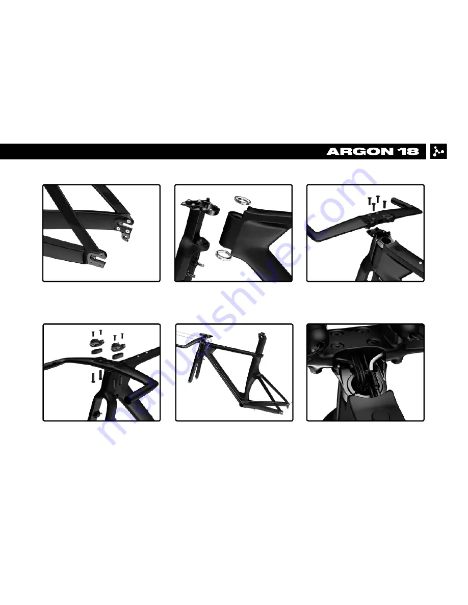
2. Fork installation

1. Frame inspection

5. Cable housing installation

IMPORTANT NOTICE: It is easier to install the 
cables and cable housings before the bearings.

6.  Electronic drive-train 

specification

3. Handlebar installation

4. Handlebar assembly

2

E-118 NEXT 216A: Assembly overview

Summary of Contents for 216A

Page 1: ...E 118 NEXT 216A ASSEMBLY GUIDE Revision 6 0 05 03 2017...

Page 2: ...bly 26 10 Seatpost installation 27 11 Saddle adjustment 28 29 12 Derailleur hanger adjustment 30 13 Parts SKUs and Descriptions 31 34 E 118 NEXT 216A Table of contents For the warranty to be valid the...

Page 3: ...Cable housing installation IMPORTANT NOTICE It is easier to install the cables and cable housings before the bearings 6 Electronic drive train specification 3 Handlebar installation 4 Handlebar assem...

Page 4: ...9 Armrest assembly 12 Derailleur hanger adjustment 10 Seatpost installation 11 Saddle adjustment 3 E 118 NEXT 216A Assembly overview 8 Rear brake installation 7 Front brake installation...

Page 5: ...13 Parts listing 4 E 118 NEXT 216A Assembly overview...

Page 6: ...nger Screw 2 3mm 4Nm Loctite 2 Rear derailleur hanger Screw 2 3mm 4Nm Loctite 3 Bottle cage Screw 4 4mm 3Nm Grease 4 Bottom bracket cover Screw 2 5mm 2Nm Grease When assembling a new frame be sure to...

Page 7: ...and 26 MR122 1 1 8 inside the frame after greasing the surfaces 2 2 Install the fork by placing the lower part first and then balancing the upper part in its final position 6 E 118 NEXT 216A 2 Fork i...

Page 8: ...the compression column 4b specific to the size of your frame inside the head tube The threads must be lightly greased until the compression column can be inserted smoothly and tightly 2 5 Screw in th...

Page 9: ...se the desired position of the handlebar high 2 5cm or low 2 5cm 3 2 Apply grease on the 4 screws 6 M6x22mm and tighten them at 6Nm in an alternate way 8 E 118 NEXT 216A 3 Handlebar installation 6 GRE...

Page 10: ...tall vertical spacers 17 and two sleeve nuts 15 See next page for stack configuration options 9 E 118 NEXT 216A 3 Handlebar installation continued 15 17 GREASE 5Nm 5Nm 5Nm 5Nm CARBON FIBER ASSEMBLY CO...

Page 11: ...nut 50mm 50mm 50mm 50mm 50mm 80mm 80mm Screw flat head 15mm 25mm 25mm 35mm 35mm 15mm 15mm Total stack height mm 70 75 80 85 90 95 100 WITH SWIVEL Required spacer 10 40 5 10 40 20 40 5 20 40 70 5 70 10...

Page 12: ...to fix the flat head screw at 6Nm Once the proper angle is set use a marker to obtain a reference and ajust both spacers with same angle Use the Di2 hole as a starting point Fix the 6mm flat head of...

Page 13: ...center of the spacers Make sure the D12 cable goes through the bottom notch Drop the cable in the handlebar using the hole between the two sleeve nuts Run the cable inside the handlebar until it come...

Page 14: ...in lenght The cut must be made on the elbow side The other end of the bar is used exclusively to install the shifter Apply some carbon fiber assembly gel in the clamping area Warning If using a ski be...

Page 15: ...9 over the extension bars Tighten the screws 13 at 5Nm The connector bridge can be installed in two distinct positions long or short cockpit 9 Note Cyclometer support Install the cyclometer support be...

Page 16: ...e image A page 16 5 4 Install the rear brake cable housing starting under the bottom bracket shell See the table below for the cable housing length suggested Suggested lengths of the cable housing the...

Page 17: ...es Follow the curves of the handlebar Once the cable is out slide the cable housing along IMPORTANT You must cut the metal ferrule located at the end of the rear brake EZ Bend cable housing prior to i...

Page 18: ...ain specification The Di2 cable routing can be achieve easily using this simple trick use a brake cable and a metal cable end to fix the Di2 cable For more information on Shimano Di2 electronic system...

Page 19: ...18 E 118 NEXT 216A 6 Electronic drive train specification Use the proper grommet on the top tube to fix the cable correctly depending if you use electronic shifting or mechanical drive train 19c 19d...

Page 20: ...ain specification The Di2 battery can go either under the left chainstay Shimano SM BTR1 or inside the seatpost Shimano SM BTR2 by using the Di2 battery older 30 For this configuration apply a slight...

Page 21: ...20 E 118 NEXT 216A 6 Electronic drive train specification Use the proper grommet for the front derailleur cable depending if you use mechanical 19b or electronic drive train 19a 19b 19a...

Page 22: ...required use the outer hole 7 2 It is important not to mix the springs of the front and rear brakes 7 3 Respect the colour code the spring must be installed on the pivot of the same colour 21 8Nm 8Nm...

Page 23: ...ng inside the head tube the cable and cable housing must go through the front part of the frame Pass the cable through the curved straw and then in the appropriate guide Make sure that the length of t...

Page 24: ...brake pad spacing with 1mm 25f 2mm 25g or no spacers behind the brake pads depending of the rim width you are using 23 25f 25g Spacers required according to the rim width Rim width Spacer combinaison...

Page 25: ...ing the crankset 8 3 Install the brake arm stopper 2i and adjust the set screw 24k after the wheel is put in place to avoid any contact between the brake arm stopper and the crankset It is important n...

Page 26: ...n the cover of the plastic cable guide 2e as shown in the diagram Apply gentle pressure on the cover and tighten the three screws in to 2Nm keeping the middle screw for last A hex key supplied with th...

Page 27: ...sts 10 11 9 2 Screw the armrests 10 11 into the extension bar connector bridge 13 at 5Nm in the position desired Reverse the left and the right armrests to obtain a more forward or backward setup 9 3...

Page 28: ...read 3b 10 2 Place the seat clamp thread 3b inside the frame 10 3 Insert the seatpost 20 on which some carbon fiber assembly gel has been applied 10 4 Position the seatpost to the desired height and i...

Page 29: ...ghten the upper screw of the rocker clamp 20a by keeping a space of 2 to 3 mm between the aluminum and carbon parts 11 3 Adjust the angle of the saddle and tighten the lower screw of the rocker clamp...

Page 30: ...ustment The 2waypost ASP 7500 can be flipped to achieve a triathlon or a road position 75 78 The seat clamp offset can be set by flipping the rail clamp 20d and the rocker 20f Road 10mm to 15mm Tri 10...

Page 31: ...nt The front derailleur hanger can be adjusted according to the front derailleur angle to get an equal curve between the derailleur and the big chain ring Once at the right angle use blue 242 Loctite...

Page 32: ...80070 M 80069 L 80068 36714 black 36715 silver 39005 black 39006 silver XS FK E118N XS 216A S FK E118N S 216A M FK E118N M 216A L FK E118N L 216A 38987 36618 38933 36716 36602 38968 36716 38916 80382...

Page 33: ...mp Screw incl washer Fork 38987 1 2a Rear Derailleur Hanger Assembly Frame 38175 1 2b Front Derailleur Hanger Assembly Frame 36197 1 2d Bottle Cage Screws Frame 38234 5 2e Bottom Bracket Cover incl sc...

Page 34: ...ar 38916 2 14c Swivel Screw M6x12mm Handle Bar 38911 2 14e Swivel Square Nut Handle Bar 80382 2 15a 20mm Sleeve Nut Handle Bar 38917 4 15b 30mm Sleeve Nut Handle Bar 38918 4 15c 50mm Sleeve Nut Handle...

Page 35: ...set 23 Tektro RL977 Brake levers Handle Bar 37470 1 set 24 Rear Brake TKB77 incl all hardware Frame 36602 1 set 24c Rear Brake Noodle 125 degrees 36713 1 24d Springs 36714 black 1 36715 silver 1 24f 2...

Reviews: