


8
connEcTing ELEcTricAL poWEr suppLy
Wiring THE BoiLEr
!
WARNING
Do not use aluminum wire!!
Argo Electric Hydronic Boilers are pre-wired for use with
240-volt, 3 wire, single-phase, 50/60-hertz power. See
Table A on page 4 for reduction in boiler capacity when line
voltage is less than 240 volts.
Opening provided in jacket bottom panel for field wiring,
refer to rating chart for recommended wire sizes.
Electrical wiring shall be done in accordance with Canadian
Electrical Code, CSA C22.1 Part 1, authority having
jurisdiction in Canada, or National Electrical code, ANSI/
NFPA 70 and/or authority having jurisdiction in USA. Verify
nameplate rating and check related codes to properly size
conductors, switches and over current protection. Several
openings are provided on bottom of cabinet for different
voltage connections. Wire connections refer to wiring
diagram on inside of boiler front cover.
All circuit breakers or disconnects ahead of boiler must
be OFF. If boiler contains integral breakers (depending on
option), it is recommended they are also turned off at this
time. Remove boiler front cover by removing 4 screws from
top and sides.
If boiler is used in multiple zone system, the zone valves
must be powered from independent source and have
electrically isolated end switches or isolating relays wired in
parallel to boiler thermostat terminals.
Do not attempt to
power zone valves from transformer in boiler control
system!!
Wiring on conTroL
PUmP:
Connect only 120 Vac 1/6 HP (maximum)
pump to terminals C1(L) and C2(N) on controller. Strip
wire ends before inserting into terminal block. Tighten
terminal screws.
Do not use pump rated greater
than 5 amps!!
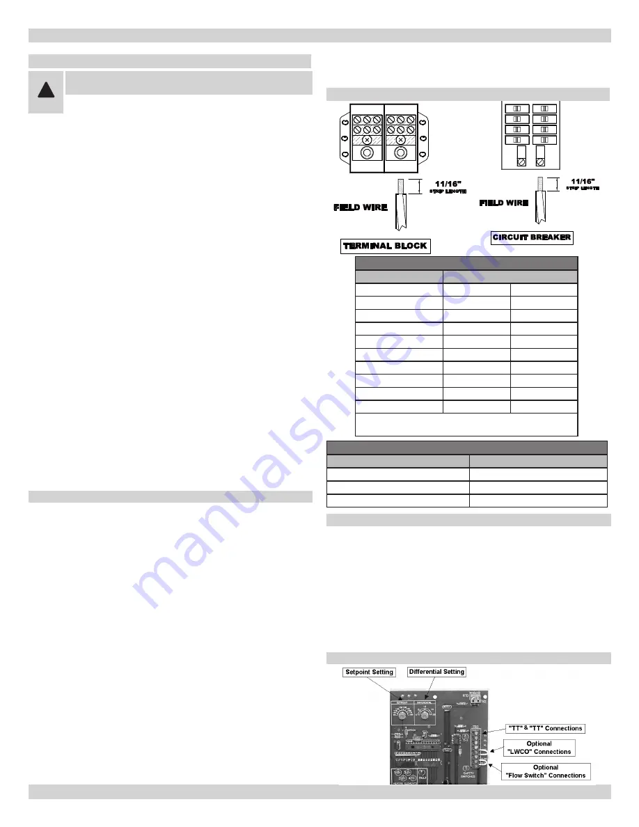
tHERmoStat:
Connect thermostat or zone valve
end switch to terminals TT and TT
(Figure 4)
.
Do not
apply external power source to terminals!!
Strip
wire ends before inserting into terminal block. Tighten
terminal screw clamps.
Field Wire Line Side Torque Specifications -
table C
Wire Size (AWG)
Torque requirements (in LBS)
2/0-6
120
8
40
10-14
35
figurE 4
fiELd Wiring
Wire Classes - Table B
Number of Concentric Strands
Wire Size AWG
Class B
Class C
10
7
19
8
7
19
6
7
19
4
7
19
3
7
19
2
7
19
1
19
37
1/0
19
37
2/0
19
37
Class B - Power cables
Class C - Power cables where more flexibility is desired
All Field wiring shall be in accordance with NEC or CEC
•
standards. Minimum Circuit Ampacity (MCA) and recom-
mended Maximum Overcurrent Protection (MOP) are list-
ed on nameplate of unit, see Table A.
Use Copper conductors only.
•
Use only Class B or C Stranded wire. See Table B.
•
Wire Strip Length: 11/16” (Minimum). (Refer to field wir
-
•
ing diagram).
Wire must be fully inserted into terminal block, touching
•
back of entrance hole.
Field terminal wire lugs shall be tightened in accordance
•
with manufacture's recommended torque specifications
using appropriate torque wrench. Proper toque settings
are listed on terminal block, see Table C.
Hex head wrench size required for Terminal Block: 5/16”.
•
For Circuit Breaker: Flat Screwdriver.
Do not use wire grease on wire termination connections
•
and terminal block. This will change torque properties.
The Terminal block was not tested or approved using wire
grease.
fiELd Wiring diAgrAm
Hold lug at specified torque for 5 seconds before releasing.
•
When tightening this will ensure any cold flow of material
is compensated for.