background image

140

PR773A

3. Place the tie rod ends into the knuckles and secure

with the castle nuts (coated with red Loctite #271).

Tighten to 30 ft-lb; then install new cotter pins.

NOTE: If the slots in the castle nut are not

aligned with the hole in the tie rod end, tighten
until the cotter pin can be installed.

4. Install the EPS assembly (see Installing EPS Assem-

bly sub-section in this section); then tighten the cap

screws (from step 2) to 20 ft-lb.

5. Install the wheel and tighten to 80 ft-lb.

Steering Wheel

REMOVING

1. Remove the steering wheel cover; then match mark

the steering shaft and steering wheel.

NOTE: Any time steering components are disas-

sembled, all connecting components should be
marked for proper alignment during assembling.

2. Remove the lock clip from the steering shaft; then

remove the nut securing the steering wheel and

remove the steering wheel.

INSPECTING

1. Inspect the steering wheel for cracks, missing pad-

ding, or broken spokes.

2. Inspect the splines for wear.

3. Check that the steering wheel is not bent.

INSTALLING

1. Install the steering wheel aligning the two match

marks; then apply a drop of red Loctite #271 to the

threads of the nut and secure the steering wheel.

Tighten to 25 ft-lb.

NOTE: If a new steering wheel is being installed,

mark the wheel as close as possible to the old
wheel mark; then check for proper positioning with
the front wheels straight forward.

2. Install the lock clip on the steering shaft.

NOTE: If the hole in the steering shaft does not

align with the slots in the castle nut, tighten the
nut slightly until the next slot aligns with the hole.

HDX131A

Upper Steering Shaft

REMOVING

1. Remove the dashboard (see Dashboard in this sec-

tion).

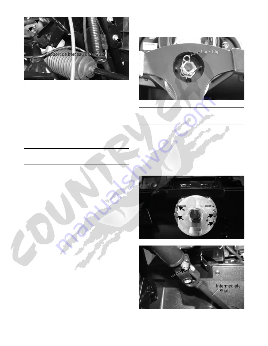
2. Remove the four cap screws and nuts securing the

steering shaft housing to the steering support; then

remove the cap screw securing the intermediate shaft

yoke to the steering shaft.

PR764A

PR765A

3. Remove the steering shaft housing and shaft from the

steering support and intermediate shaft; then remove

the intermediate shaft from the EPS input shaft.

Summary of Contents for ROV 2013

Page 1: ......

Page 2: ...int to emphasize important information The symbol WARNING identifies personal safety related information Be sure to fol low the directive because it deals with the possibility of serious personal injury or even death A CAUTION identi fies unsafe practices which may result in vehicle related damage Follow the directive because it deals with the possibility of damaging part or parts of the vehicle T...

Page 3: ......

Page 4: ...id Cooling System 70 Radiator 70 Thermostat 72 Fan 72 Water Pump 72 Electric Fuel Pump Fuel Level Sensor 73 Troubleshooting 75 Electrical System 76 Battery 76 RPM Limiter 77 Testing Electrical Components 77 Switches 77 Electrical Connections 77 Accessory Receptacle Connector 77 Brakelight Switch 77 Engine Coolant Temperature ECT Sensor 78 Fan Motor 78 Power Distribution Module PDM 79 Ignition Coil...

Page 5: ...sition Sensor AC Voltage 2 0 or more blue to green AC Generator Output no load 60 AC volts 5000 RPM yellow to yellow Ignition Timing 10 BTDC 1500 RPM VALVES AND GUIDES Valve Face Diameter intake exhaust 31 6 mm 27 9 mm Valve Tappet Clearance intake cold engine exhaust 0 1016 mm 0 1524 mm Valve Guide Stem Clearance 0 013 mm Valve Guide Valve Stem Deflection max wobble method 0 35 mm Valve Guide Ins...

Page 6: ...ential Gear Case Frame 38 48 Drive Coupler Front Front Drive Flange 40 54 Front Engine Mounting Bracket Frame 45 61 Rear Engine Mounting Bracket Frame 45 61 Engine Mounting Through Bolt Frame 40 54 Front Differential Frame Differential Bracket 38 52 Rear Output Flange Rear Driven Flange 40 54 Input Shaft Assembly Gear Case Housing 23 31 Pinion Housing Differential Housing 23 31 Secondary Shaft Bea...

Page 7: ...ted gasolines containing up to 10 ethanol or 5 methane are acceptable gasolines When using ethanol blended gasoline it is not necessary to add a gasoline antifreeze since ethanol will prevent the accumulation of moisture in the fuel system RECOMMENDED ENGINE TRANSMISSION OIL The recommended oil to use is Arctic Cat ACX All Weather synthetic engine oil which has been specifi cally formulated for us...

Page 8: ...stall the air filter and housing cover 4 Plug the exhaust hole in the exhaust system with a clean cloth 5 Apply light oil to the plungers of the shock absorb ers 6 Tighten all nuts bolts cap screws and screws Make sure rivets holding components together are tight Replace all loose rivets Care must be taken that all calibrated nuts cap screws and bolts are tightened to specifications 7 Fill the coo...

Page 9: ...s headlights taillight brakelight and headlight aim adjust or replace as necessary 8 Tighten all nuts bolts cap screws and screws mak ing sure all calibrated nuts cap screws and bolts are tightened to specifications 9 Check tire pressure Inflate to recommended pres sure as necessary 10 Make sure the steering moves freely and does not bind 11 Check the spark plug Clean or replace as necessary CAUTI...

Page 10: ...255 Item Initial Service After Break In First Month or 100 Miles Every Day Every Month or Every 100 Miles Every 3 Months or Every 300 Miles Every 6 Months or Every 500 Miles Every Year or Every 1500 Miles As Needed Battery I I C Fuses I R Air Filter I I R Valve Tappet Clearance I I A Engine Compression I Spark Plug I I I R 4000 Mi or 18 Mo Muffler Spark Arrester C R Gas Hoses I I R 2 Yrs Throttle ...

Page 11: ...e use the fol lowing procedure NOTE The engine must be cold for this procedure NOTE The seat seat back seat base and spark plug must be removed for this procedure 1 Remove the spark plug and timing inspection plug then remove the tappet covers for more detailed informa tion see the Engine Transmission section Servicing Top Side Components 2 Rotate the crankshaft to the TDC position on the compress...

Page 12: ...or an accurate compression test The throttle must be in the wide open throttle WOT position In the event the engine cannot be run cold values are included NOTE The seat seat back and seat base must be removed for this procedure 1 Remove the high tension lead from the spark plug 2 Using compressed air blow any debris from around the spark plug 3 Remove the spark plug then attach the high tension le...

Page 13: ...ing care not to damage the screen NOTE If the screen or gasket is damaged in any way it must be replaced 3 Install the spark arrester assembly and gasket and secure with the cap screws Tighten the cap screws to 48 in lb Engine Transmission Oil Filter OIL FILTER Change the engine oil and oil filter at the scheduled inter vals The engine should always be warm when the oil is changed so the oil will ...

Page 14: ... must be within the operating range but not exceeding the upper mark GZ461A 10 Inspect the area around the drain plug and oil filter for leaks Front Differential Rear Drive Lubricant To check lubricant use the following procedure 1 Remove the fill plug the lubricant level should be one inch below the plug threads PR530A 2 If low add SAE approved 80W 90 hypoid gear lube as necessary To change the l...

Page 15: ...connector from the back of the headlight 2 Grasp the bulb socket turn it counterclockwise and remove and pull the bulb straight out of the socket 3 Install the new bulb into the socket and rotate it com pletely clockwise in the housing 4 Install the wiring harness connector TAILLIGHT BRAKELIGHT To replace the taillight brakelight bulb use the following procedure 1 Remove the two machine screws and...

Page 16: ...to high range and look for the H indication low range for the L indication and reverse for the R indication 2 Shift the transmission into park and observe that the P illuminates on the LCD gauge ADJUSTING SHIFT CABLE To adjust the shift cable use the following procedure 1 Place the transmission in park then tilt the cargo box 2 Make sure the shift lever is in park then remove the E clip securing t...

Page 17: ...lways a sufficient amount of brake fluid When the level falls below MIN refill the reservoir before the bleeding procedure is continued Failure to main tain a sufficient amount of fluid in the reservoir will result in air in the system D At this point perform steps B and C on the other FRONT bleeder screw then move to the REAR bleeder screw s and follow the same procedure E Repeat steps B and C un...

Page 18: ...iveness Braking distance will be extended until brake pads are properly burnished To properly burnish the brake pads use the following procedure 1 Choose an area large enough to safely accelerate the vehicle to 30 mph and to brake to a stop 2 Accelerate to 30 mph then depress the brake pedal to decelerate to 0 5 mph 3 Repeat procedure 20 times until brake pads are bur nished Checking Replacing V B...

Page 19: ...e 271 Tighten the nut to 165 ft lb GZ485A NOTE At this point remove the cap screw from the driven pulley face 3 Rotate the V belt and driven pulley clutch until the V belt is flush with the top of the driven pulley 4 Place the V belt cover gasket into position then install the cover and secure with the cap screws mak ing sure the different lengthed cap screws are in their proper location Tighten t...

Page 20: ...xcessive Condition Remedy 1 Brake fluid low 2 Piston seal cup worn 1 Add fluid to proper level 2 Replace seal cup Problem Brake fluid leaking Condition Remedy 1 Connection fittings loose 2 Hose cracked 3 Piston seal worn 1 Tighten fittings 2 Replace hose 3 Replace seal Problem Brake pedal spongy Condition Remedy 1 Air trapped in hydraulic system 2 Brake fluid low 1 Bleed hydraulic system 2 Add bra...

Page 21: ...e removed from the frame SPECIAL TOOLS A number of special tools must be available to the techni cian when performing service procedures in this section Refer to the current Special Tools Catalog for the appro priate tool description NOTE Special tools are available from the Arctic Cat Service Department Description p n Seal Protector Tool 0444 252 Crankcase Separator Crankshaft Remover 0444 152 M...

Page 22: ...place fuel injector 5 Adjust clearance Problem Engine noisy Excessive valve chatter Condition Remedy 1 Valve clearance excessive 2 Valve spring s weak broken 3 Rocker arm rocker arm shaft worn 4 Camshaft worn 1 Adjust clearance 2 Replace spring s 3 Replace arm shaft 4 Replace camshaft Problem Engine noisy Noise seems to come from piston Condition Remedy 1 Piston cylinder worn 2 Combustion chamber ...

Page 23: ...vy Condition Remedy 1 Engine oil overfilled contaminated 2 Piston rings cylinder worn 3 Valve guides worn 4 Cylinder wall scored scuffed 5 Valve stems worn 6 Stem seals defective 1 Drain excess oil change oil 2 Replace cylinder service rings 3 Replace guides 4 Replace cylinder 5 Replace valves 6 Replace seals Problem Engine lacks power Condition Remedy 1 Valve clearance incorrect 2 Valve springs w...

Page 24: ...DX136A 5 Wrap the gasline hose connector with a shop cloth then remove the gasline hose connector from the fuel rail HDX138A 6 Loosen the clamp securing the air filter intake tube to the air filter then remove the mounting screw and remove the intake tube HDX031A 7 Remove four sheet metal screws securing the air fil ter mounting bracket to the frame then loosen the air inlet boot clamp and disconn...

Page 25: ...ring the shift cable bracket to the engine case Remove the shift cable from the shift arm and disconnect the gear position switch connec tor PR825A 11 Disconnect the starter cable from the starter then remove the cap screw securing the engine harness ground wires to the engine case HDX149A 12 Remove the CVT inlet and exhaust ducts from the V belt housing HDX146A HDX147A 13 Remove the forward heat ...

Page 26: ...gine mounts then remove the front through bolt HDX157A HDX156A 18 Attach a suitable lifting sling and with a suitable engine hoist lift the engine from the vehicle Top Side Components NOTE For efficiency it is preferable to remove and disassemble only those components which need to be addressed and to service only those components The technician should use discretion and sound judgment NOTE The en...

Page 27: ...rews securing the valve cover to the head account for the four rubber washers on the top side cap screws Remove the valve cover Account for and note the orientation of the cylinder head plug Note the location of two alignment pins CD205 CD206 CD211A 3 Loosen the cap screw on the end of the tensioner then remove the two cap screws securing the ten sioner adjuster assembly and remove the assembly Ac...

Page 28: ... sprocket and cam shaft out of the cylinder head CC266D 7 Remove the cap screw securing the chain tensioner account for a washer then remove the tensioner CC014D NOTE Loop the chain over the cylinder and secure it to keep it from falling into the crankcase 8 Remove the five nuts securing the cylinder head to the cylinder then remove the four cylinder head cap screws CC017D CC018D CC016D ...

Page 29: ... detach the hose 11 Remove the two nuts securing the cylinder to the crankcase CC023D 12 Lift the cylinder off the crankcase taking care not to allow the piston to drop against the crankcase Account for the gasket and two alignment pins CC024D CC025D CC026D AT THIS POINT To service valves and cylinder head see Servicing Top Side Components sub section AT THIS POINT To inspect cam chain guide see S...

Page 30: ...surface for any indication of high spots A high spot can be noted by a bright metallic finish Cor rect any high spots before assembly by continuing to move the valve cover in a figure eight motion until a uniform bright metallic finish is attained CC130D Removing Valves NOTE Keep all valves and valve components as a set Note the original location of each valve set for use during installation Retur...

Page 31: ...tions Measuring Valve Face Seat Width 1 Using a micrometer measure the width of each valve face ATV 1004 2 Acceptable width range intake valves must not exceed specifications 3 Acceptable width range exhaust valves must not exceed specifications Measuring Valve Face Radial Runout 1 Mount a dial indicator on the surface plate then place the valve stem on a set of V blocks 2 Position the dial indica...

Page 32: ...ide diameter of the rocker arm shaft 2 Acceptable outside diameter must be at or above specification Installing Valves 1 Apply grease to the inside surface of the valve seals then place a lower spring seat and valve guide seal over each valve guide CC144D 2 Insert each valve into its original location 3 Install the valve springs with the painted end of the spring facing away from the cylinder head...

Page 33: ... the cylinder Use the piston to position each ring squarely in the cylinder 2 Using a feeler gauge measure each piston ring end gap Acceptable ring end gap must not exceed specifications CC280D Measuring Piston Pin Outside Diameter and Piston Pin Bore 1 Measure the piston pin outside diameter at each end and in the center If measurement is not within speci fications the piston pin must be replaced...

Page 34: ...ng surface 2 Inspect the spark plug hole for any damaged threads Repair damaged threads using a heli coil insert 3 Place the cylinder head on the surface plate covered with 400 grit wet or dry sandpaper Using light pressure move the cylinder head in a figure eight motion Inspect the sealing surface for any indication of high spots A high spot can be noted by a bright metallic finish Correct any hi...

Page 35: ... from top to bottom and again from top to bottom at 90 from the first measurements for a total of six measurements The trueness out of round ness is the difference between the highest and low est reading Maximum trueness out of roundness must not exceed specifications CC127D 2 Wash the cylinder in parts cleaning solvent 3 Inspect the cylinder for pitting scoring scuffing and corrosion If marks are...

Page 36: ...found the cylinder head assembly must be replaced Measuring Camshaft to Cylinder Head Clearance 1 Remove the adjuster screws and jam nuts CC005D 2 Place a strip of plasti gauge in each of the camshaft lands in the cylinder head 3 Place the valve cover on the cylinder head and secure with the valve cover cap screws Tighten securely NOTE Do not rotate the camshaft when measur ing clearance 4 Remove ...

Page 37: ...toward the exhaust CC032D 2 Place the two alignment pins into position and place a drop of silicone sealant on case half joints Place the cylinder gasket into position then place a piston holder or suitable substitute beneath the piston skirt and square the piston in respect to the crankcase CF083 3 Lubricate the inside wall of the cylinder then using a ring compressor compress the rings and slide...

Page 38: ... CF289A 8 Install the four cylinder head cap screws Tighten only until snug CC272D 9 Loosely install the five cylinder head nuts 10 In a crisscross pattern tighten the four cylinder head cap screws from step 8 in 10 ft lb increments to 40 ft lb then tighten the 8 mm nut from step 9 to 18 ft lb Using a crisscross pattern tighten the 6 mm nuts from step 9 to 8 ft lb Tighten the two cylin der to cran...

Page 39: ...cessary for alignment rotate the sprocket inside the chain until the alignment pin can be engaged in the sprocket with the camshaft properly aligned to the head CD463 15 Seat the cam sprocket onto the camshaft making sure the alignment pin in the camshaft aligns with the smallest hole in the sprocket then place the cam shaft sprocket assembly onto the cylinder ensuring the following CF013A A Pisto...

Page 40: ...then tighten to 11 ft lb Bend the tab to secure the cap screw CD466 20 Place the C ring into position in its groove in the cyl inder head CC012D 21 Install the cylinder head plug in the cylinder head with the open end facing downward and toward the inside GZ162A 22 Remove the cap screw from the end of the chain ten sioner then using a flat blade screwdriver rotate the adjuster screw inside the ten...

Page 41: ...se until all tension is released then install the cap screw into the end of the chain tensioner CD470 CD471 25 Loosen the four adjuster screw jam nuts then loosen the four adjuster screws on the rocker arms in the valve cover CC005D 26 Apply a thin coat of Three Bond Sealant to the mat ing surfaces of the cylinder head and valve cover CC275D 27 Place the valve cover into position NOTE At this poin...

Page 42: ...removed from the frame for this procedure Removing Left Side Components A Water Pump B Side Cover C Rotor Flywheel 1 Remove the four screws securing the outer magneto cover to the side cover then remove the cover 2 Remove the flange nut securing the spacer to the crankshaft then remove the spacer Account for the O ring PR465 3 Using a cold chisel scribe a mark showing the rela tive position of the...

Page 43: ...ing purposes 8 Using a side case puller remove the side cover Account for a gasket and two alignment pins NOTE Inspect the inside of the right side cover for any shaft washers that may have come off with the cover Make sure they are returned to their respective shafts and the starter idler gear spacer is on the shaft or in the cover CF075A 9 Remove the nut securing the magneto rotor to the cranksh...

Page 44: ...ignment pin into the crankcase 14 Remove the shift shaft noting the timing marks for assembling purposes Account for two washers PR430A 15 Remove the gear shift cam plate then remove the shift cam stopper and cam stopper spring Account for two washers PR434A Servicing Left Side Components INSPECTING STARTER CLUTCH GEAR 1 Place the starter clutch gear onto the rotor flywheel and attempt to rotate t...

Page 45: ...h the cap screws after applying a drop of red Loctite 271 to the threads Tighten to 26 ft lb using a crisscross pattern Make sure the one way bearing is installed with the notches directed away from the rotor flywheel FI576A FI578 REPLACING STARTER GEAR BEARING 1 Support the starter clutch gear in a press making sure to support the hub around the entire circumference then using a suitable bearing ...

Page 46: ...position of the harness hold down under the crankshaft position sensor FI590 3 Install the new stator coil assembly and secure with three cap screws using a drop of blue Loctite 243 on each Tighten to 13 ft lb 4 Place the stator wire harness hold down into posi tion then install the crankshaft position sensor and secure with two cap screws Tighten securely 5 Install the upper cable hold down and s...

Page 47: ...secured remove the oil passage plug from the crankcase 3 Install the two starter gear shafts then install the two starter gears with the beveled side of the intermedi ate gear facing inward as noted in removing CD139 PR447A 4 In order on the crankshaft install a washer ring gear key and the magneto rotor Secure with the nut threads coated with red Loctite 271 Tighten to 105 ft lb CD948A CD940B 5 I...

Page 48: ...ion on the two alignment pins Make sure the outer shift shaft washer is in place PR431A 9 Install the magneto cover and secure with the cap screws Tighten only until snug 10 Place the spacer into position on the crankshaft mak ing sure a new lubricated O ring is inside the spacer Tighten the flange nut to 28 ft lb PR465 11 Tighten the cap screws from step 9 to 8 ft lb 12 Clean the countershaft and...

Page 49: ...referable to remove and disassemble only those components which need to be addressed and to service only those components The technician should use discretion and sound judgment NOTE The engine transmission does not have to be removed from the frame for this procedure Removing Right Side Components A V Belt Cover B Driven Pulley C Clutch Cover 1 Remove the cap screws securing the V belt cover noti...

Page 50: ...93 6 Remove the cap screws securing the clutch cover Note the location of the different lengthed cap screws for installing purposes Using a rubber mallet carefully remove the cover Account for two align ment pins CD973A CD974A NOTE For steps 7 13 refer to illustration PR398B NOTE To aid in installing it is recommended the assemblies are kept together and IN ORDER CAUTION Care must be taken when re...

Page 51: ...acer and an O ring inside the fixed drive spacer CF085 CC596 NOTE Account for and inspect the clutch hous ing seal CF088A 9 Remove the nut left hand threads securing the clutch shoe assembly C FI279A 10 Remove the cap screw securing the oil pump drive gear B Account for a cap screw washer pin and spacer CC606 CD987 KEY A Oil Pump Driven Gear B Oil Pump Drive Gear C Clutch Shoe Assembly D One Way C...

Page 52: ...Remove the cap screws securing the oil pump then remove the pump CD988 Servicing Right Side Components NOTE Whenever a part is worn excessively cracked damaged in any way or out of tolerance replacement is necessary INSPECTING CENTRIFUGAL CLUTCH SHOE 1 Inspect the clutch shoes for uneven wear chips cracks or discoloration If any shoe is damaged replace the complete set 2 Inspect the clutch shoes f...

Page 53: ...ed CD988A DRIVEN PULLEY NOTE The driven pulley is a non serviceable component If pulley faces cam ramps or sheave bushings are worn the assembly must be replaced Do not to disassemble the driven pulley Installing Right Side Components 1 Install the secondary shaft bearing housing making sure the two alignment pins are properly positioned Tighten the cap screws to 28 ft lb CD999 2 Install the oil p...

Page 54: ...ll the clutch shoe assembly and secure with the flange nut threads coated with red Loctite 271 Tighten to 221 ft lb PR410A 6 Install the clutch cover alignment pins into the crank case apply oil to the cover gasket and install the gasket onto the crankcase 7 Install the one way clutch onto the clutch shoe assembly PR399A 8 Lightly grease the clutch housing seal then insert the left fixed drive spa...

Page 55: ... securely CD971 CD970 12 Place the driven pulley assembly into position and secure with the nut Using Spanner Wrench tighten to 80 ft lb 13 Slide the fixed drive face onto the shaft 14 Spread the faces of the driven pulley by threading a 6 mm cap screw into the threaded boss then turn clockwise until pulley faces are opened approxi mately 1 2 in 15 Place the V belt into position on the driven pull...

Page 56: ...scretion and sound judgment Separating Crankcase Halves 1 Remove the left side cap screws securing the crank case halves Note the location of the different lengthed cap screws 2 Remove the right side cap screws securing the crankcase halves Note the location of the different lengthed cap screws 3 Using the Crankcase Separator Crankshaft Remover and tapping lightly with a rubber mallet separate the...

Page 57: ...e two holes on the end of the shaft Account for a washer and a spacer DE677A 5 Remove the countershaft assembly D Account for a washer on each end of the countershaft CC674 NOTE Do not disassemble the countershaft assembly unless necessary If necessary see Ser vicing Center Crankcase Components sub sec tion 6 Using a rubber mallet tap on the crankcase to remove the driveshaft E CC675 7 Note the ti...

Page 58: ...NOTE If the secondary output driven shaft is replaced or disassembled the initial set up must be performed to establish correct gear tooth con tact If only the secondary output driveshaft or secondary output driven gear are replaced pro ceed to Correcting Backlash in this sub section 1 Install a new bearing A onto the secondary driven shaft B making sure the bearing locating groove is directed awa...

Page 59: ... bevel gear shaft into the crankcase then tighten the nut to 59 ft lb 2 Install the secondary drive bearing support then install the secondary driven output shaft into the crankcase 3 Mount the dial indicator so the tip is contacting a tooth on the secondary drive bevel gear 4 While rocking the drive bevel gear back and forth note the maximum backlash reading on the gauge MT005A 5 Acceptable backl...

Page 60: ...nd of the con necting rod away from the dial indicator 3 Maximum deflection must not exceed specifications Measuring Connecting Rod Big End Side to Side 1 Push the lower end of the connecting rod to one side of the crankshaft journal 2 Using a feeler gauge measure the gap between the connecting rod and crankshaft journal CC289D 3 Acceptable gap range must not exceed specifica tions Measuring Crank...

Page 61: ...snap ring securing the reverse driven gear dog and bushing to the countershaft GZ296 GZ312 3 Remove the reverse driven gear dog GZ313A 4 Remove the snap ring securing the reverse driven gear and washer then remove the washer and gear GZ314 CAUTION When disassembling the countershaft care must be taken to note the direction each major component dog gear faces If a major component is installed facin...

Page 62: ... low driven gear Account for a bearing bushing and thrust washer GZ316 Assembling 1 From the drive gear end install a thrust washer bushing and bearing then install the low driven gear and washer GZ317A GZ318 2 Install the low driven gear locking washer then install the inner reverse driven gear washer GZ319B GZ320B ...

Page 63: ...ft and secure with a snap ring GZ313A GZ312 6 From the opposite end of the countershaft install the high low driven gear dog A thrust washer B bushing C bearing D high low driven gear E and spacer washer F GZ283B 7 Install the drive gear washer and the shift forks The countershaft is now ready for installation NOTE When installing the countershaft assem bly account for the washer on each end of th...

Page 64: ... balancer CD832B NOTE It will be necessary to rotate the crank bal ancer until the counterweight is facing away from the crankshaft then rotate the crankshaft clock wise into the journal area to allow the crank bal ancer to be fully seated 4 Place the key into the crank balancer keyway then install the crank balancer gear making sure the align ment dots on the crank balancer gear and the crank sha...

Page 65: ...g C ring is fully seated in the crankcase CD268A 11 Place the oil strainer into position then secure with the two screws 12 Place the oil strainer cap into position making sure the O ring is in position then secure the cap with cap screws Tighten securely Joining Crankcase Halves 1 Apply High Temp Sealant to the right side mating surface smoothing out any build up or bumps 2 Lightly oil all bearin...

Page 66: ...emove the plugs from the oil cooler lines and connect to the appropriate fittings Secure with hose clamps and tighten securely 4 Secure the front and rear driveshafts to the engine flanges with the cap screws and tighten to 20 ft lb then connect the upper and lower coolant hoses and tighten the clamps securely 5 Place a new grafoil seal in the cylinder head and a new grafoil seal on the muffler en...

Page 67: ...tion switch connector PR825A 10 On the left side connect the ECT sensor connec tor speed sensor connector and spark plug cap HDX135A HDX137A 11 Install the throttle body into the intake manifold boot and secure with the clamp Tighten to 30 in lb 12 Install the air filter assembly and secure to the frame with four sheet metal screws then secure the intake boot with the clamp and tighten securely HD...

Page 68: ...e recommended amount of oil and coolant into the engine and radiator then loosen the cool ant bleed screw to allow trapped air to escape When clear coolant flows tighten the bleed screw HDX158B 17 Connect the negative battery cable to the battery and install the battery cover 18 Install the center skid plate center floorboard and seat base then install the seat back and seat 19 Start the engine an...

Page 69: ...n the ignition switch to the OFF position then remove the ignition switch key 2 Remove the seat seat back and seat base then dis connect the battery 3 Remove the air inlet boot between the air filter and throttle body then disconnect the MAP sensor con nector A fuel injector connector B and ISC con nector C HDX048A HDX043A 4 Remove the screw from the throttle arm cover and remove the cover then lo...

Page 70: ...MOVING 1 Remove the seat seat back and seat base then remove the floorboard 2 Disconnect the vent hose A gasline hose B and fuel pump fuel level sensor connector C then cap the vent fitting and gas hose fitting PR698A 3 Remove the outer cap screw securing the front tank hold down then swing the hold down to the left PR167A PR170 4 Remove four press nuts securing the gas cap filler panel then remov...

Page 71: ...the fuel level sensor for proper operation see Fuel Level Sensor in this section INSTALLING 1 Place the gas tank into position in the vehicle then install the inside rear hold down strap PR173 PR699A 2 Swing the front hold down to the right into position and install the cap screw and nut Do not tighten at this time PR171 3 Install the rear hold down strap joining cap screw and nut Do not tighten a...

Page 72: ...r this test 1 Remove the seat seat back and seat base 2 Using a suitable T fitting connect Oil Pressure Test Kit to the oil fitting and hose Tighten all clamps securely NOTE Some oil seepage may occur when install ing the oil pressure gauge Wipe up oil residue with a cloth 3 Block the wheels place the transmission in neutral and start the engine Allow the engine to warm up to operating temperature...

Page 73: ...reeze While the cooling system is being filled air pockets may develop therefore open the bleed screw on the thermostat housing to allow air to bleed from the cooling system When clear coolant no bubbles is pres ent tighten the bleed screw securely then fill the cooling system to the bottom of the stand pipe in the radiator neck Run the engine for five minutes after the initial fill shut the engin...

Page 74: ...stalled then secure to the mounts with the two shoulder bolts and nuts Tighten securely PR184A 2 Connect the upper and lower coolant hoses to the radiator and secure with the appropriate hose clamps then connect the cooling fan wire connector to the main harness PR183A 3 Open the high point bleed screw on the thermostat housing to allow trapped air to escape Tighten securely after filling 4 Pour t...

Page 75: ...secure the thermostat housing to the cylinder head with the two cap screws PR281A 2 Fill the cooling system with the recommended amount of antifreeze Check for leakage Fan REMOVING 1 Remove the radiator see Radiator in this section 2 Remove the fan assembly from the radiator INSTALLING 1 Position the fan assembly on the radiator then secure with existing hardware NOTE The fan wiring must be in the...

Page 76: ...eat base seat back and seat Electric Fuel Pump Fuel Level Sensor NOTE Preliminary checks may be performed on this component using the diagnostic mode on the LCD gauge see EFI Diagnostic System in the Electri cal System section The electric fuel pump and fuel level sensor are not ser viceable components If either component fails it must be replaced TESTING 1 Turn the ignition switch ON and listen f...

Page 77: ... the float lever and check for free movement The float assembly should return to the lower posi tion without force If not replace the fuel level sen sor assembly 3 Test the fuel level sensor by connecting a multimeter A to the fuel level sensor leads B then select OHMS The multimeter should show 5 ohms at full fuel position C and 95 ohms at empty fuel position D ATV2116 NOTE If readings are errati...

Page 78: ...gative battery cable then turn the ignition switch to the ON position and verify that no gas leaks are present the pump runs for 2 3 seconds and the gas gauge reading is normal 4 Start the engine to verify proper engine operation then shut off the engine and install the seat base seat back and seat Troubleshooting Problem Starting impaired Condition Remedy 1 Gas contaminated 1 Drain gas tank and f...

Page 79: ...ies not used for more than two weeks or as required by battery drain 1 When charging a battery in the vehicle be sure the ignition switch is in the OFF position NOTE Be sure to maintain the fluid of the battery at the UPPER LEVEL Use only distilled water when adding fluid to these batteries 2 Clean the battery terminals with a solution of baking soda and water 3 Be sure the charger and battery are...

Page 80: ...ng Electrical Components All of the electrical tests should be made using the Fluke Model 73 Multimeter or Model 77 Multimeter and when testing peak voltage the Peak Voltage Reading Adapter must be used If any other type of meter is used readings may vary due to internal circuitry When troubleshooting a specific component always verify first the fuse s are good the bulb s are good the connections ...

Page 81: ...LCD gauge see EFI Diagnostic System in this sec tion 1 Connect the meter leads selector in OHMS position to the sensor terminals 2 Suspend the sensor and a thermometer in a container of cooking oil then heat the oil NOTE Neither the sensor nor the thermometer should be allowed to touch the bottom of the con tainer or inaccurate readings will occur Use wire holders to suspend the sensor and thermom...

Page 82: ... meter must show battery voltage from one side of the connector terminal ends NOTE Battery voltage will be indicated from only one side of the fuse holder connector terminal the other side will show no voltage NOTE When testing the HI fuse holder the head light OFF HI LO switch must be in the HI position when testing the LIGHTS fuse holder the headlight dimmer switch can be in either the HI or the...

Page 83: ...his component using the diagnostic mode on the LCD gauge see EFI Diagnostic System in this sec tion 1 Disconnect the MAP connector from the pressure sensor located on the throttle body 2 Select DC Voltage on the tester and turn the ignition switch to the ON position 3 Connect the black tester lead to the black green wire and the red tester lead to the orange blue wire The meter should read 4 5 5 5...

Page 84: ... Distribution Module PDM If a system malfunction occurs a diagnostic trouble code DTC will be displayed on the LCD gauge Initially the gauge will go blank for 30 seconds and the code will flash then the gauge will return to normal except the code will continue to be displayed The following is a list of conditions that can generate a code NOTE The EPS assembly is not serviceable and must not be dis...

Page 85: ...1 Connect the red meter lead to the gray wire then connect the black meter lead to the black wire 2 Turn the ignition switch to the ON position The meter must show battery voltage NOTE If the meter does not show battery volt age troubleshoot the LIGHTS fuse on the power distribution module the ignition switch or the main harness 3 Connect the red meter lead to the yellow wire then select the high ...

Page 86: ...ely 1 5 DC volts 5 Connect the red meter lead to the red yellow wire The meter must show approximately 1 5 DC volts Depress the reverse override switch The meter must show approximately 1 5 DC volts 6 Connect the red meter lead to the red green wire The meter should show 0 DC volts 7 Depress the reverse override switch The meter must show approximately 5 DC volts Front Drive Actuator NOTE With the...

Page 87: ... meter selector to the DC Voltage position 2 Connect the red tester lead to the positive battery post then connect the black tester lead to the nega tive battery post 3 With the engine running at a constant 5000 RPM with the headlights on the meter must show 14 15 5 DC volts NOTE If voltage is lower than specified test AC Generator No Load VOLTAGE AC Generator No Load The connector is the black th...

Page 88: ...ll the starter into the crankcase Secure with two machine screws and wiring forms 2 Secure the positive cable to the starter with the nut 3 Connect the battery TESTING VOLTAGE Perform this test on the starter positive terminal To access the terminal slide the boot away NOTE The ignition switch must be in the ON posi tion and the shift lever in the NEUTRAL position 1 Set the meter selector to the D...

Page 89: ... mode on the LCD gauge see EFI Diagnostic System in this section The regulator rectifier is located under the seat next to the battery Try to verify all other charging system components before the regulator rectifier is replaced TESTING VOLTAGE 1 Start engine and warm up to normal operating tempera tures then connect a multimeter set at the DC Voltage position to the battery as follows 2 Connect t...

Page 90: ...ver verifying ignition timing can aid in troubleshooting other components To verify ignition timing use the following procedure NOTE To check ignition timing the seat seat back and seat base must be removed 1 Attach the Timing Light to the spark plug high ten sion lead then remove the timing inspection plug from the left side crankcase cover 2 Start the engine and using the RPM function on the spe...

Page 91: ...gnal 2 High Temperature indicator on 230 degrees F 3 Thermostat opening approximately 180 degrees F indicated by a momentary drop or pause in the rising temperature reading 4 Fan ON 185 degrees F OFF 175 degrees F A fan motor B fan relay C fan fuse D wiring connections 5 High Temperature Rev Limiter 5000 RPM 230 degrees F Fuel Sensor FUEL Diagnostic Mode EFI010 Display Fuel level signal from the f...

Page 92: ...29 92 in mercury DTC P0107 P0108 Usage Verify barometric pressure signal correct Note Local barometric pressure is given in in Hg Inches of Mercury 34 millibars are equal to 1 inch of mercury Example Gauge reading in the BARO mode 974 millibars thus 974 34 28 64 in Hg Second example Local barometer reading is 29 87 in Hg therefore 29 87 X 34 1015 milli bars The gauge should be reading very close t...

Page 93: ...ce signal is detected by the ECM a diagnostic trouble code DTC will be generated in the ECM and displayed on the LCD The DTC will be displayed alternately with a wrench icon or malfunction indicator light MIL The DTC will continue to flash until the malfunction is corrected and the code cleared Code List NOTE Each of the following numerical codes will have a one letter prefix of C P or U A C prefi...

Page 94: ...84 K2 Fan Relay Control Circuit High P0485 ON K2 Fan Relay Control Circuit Low SG Open P0500 Gauge Direct Error Code N A Vehicle Speed Sensor P0508 ON C4 D3 D4 E4 Idle Air Control System Circuit Low SG P0509 ON C4 D4 Idle Air Control System Circuit High Open P0562 L1 System Voltage Low P0563 L1 System Voltage High P0601 N A ECM Memory Check Sum Error P0615 1 L3 Starter Relay Circuit P0616 ON L3 St...

Page 95: ...l be required on the multimeter leads as the following tests are made with the sensor connected 1 Connect the three wire plug to the sensor then remove the right side mounting screw securing the sensor to the rear frame CD707 2 Install the needle adapters to the multimeter leads then select DC Voltage on the multimeter 3 Connect the red tester lead to the blue brown wire B and the black tester lea...

Page 96: ...Turn the ignition switch to the ON position The meter should read approxi mately 5 0 DC volts PR538A NOTE If the meter does not read as specified check for poor connections at the ECM or open broken wires in the wiring harness 4 Turn the ignition switch to the OFF position 5 Select the OHMS position on the meter then per form the following resistance tests on the TPS PR535A NOTE If any meter readi...

Page 97: ...the screw securing the TPS to the throttle body and remove the TPS INSTALLING ADJUSTING 1 Place the TPS into position on the throttle body and secure with the screw Do not tighten at this time 2 Connect the TPS Multi Analyzer Harness connector 8 to the TPS then connect the harness to the TPS Analyzer Tool FI672 3 Using a multimeter connect the black tester lead to the white socket VAR on the analy...

Page 98: ...eplace battery Problem Magneto overcharges Condition Remedy 1 Battery short circuited 2 Regulator rectifier defective 3 Regulator rectifier poorly grounded 1 Replace battery 2 Replace regulator rectifier 3 Clean tighten ground connection Problem Charging unstable Condition Remedy 1 Lead wire intermittently shorting 2 Magneto internally shorted 3 Regulator rectifier defective 1 Replace lead wire 2 ...

Page 99: ...each time the drive select switch is shifted If no sound is heard see the Electrical System section If the actuator runs constantly or makes squealing or grinding sounds the actuator must be replaced REMOVING 1 Select LOCK on the drive select switch then discon nect the connector on the actuator harness 2 Using a T 30 torx wrench remove the mounting cap screw from the driveshaft side of the actuat...

Page 100: ...e with a nylon cable tie Front Differential REMOVING 1 Remove the belly panel then place the vehicle on jack stands adjusted high enough to allow working from the underside of the vehicle NOTE The jack stands should be placed under the main frame to avoid contact with front suspension components 2 Remove the drain plug and drain the gear lubricant into a drain pan then install the plug and tighten...

Page 101: ...t allow it to drop or hang 11 Remove the lower shock cap screws Account for the lock nuts then move the shocks and upper A arm up and secure them with a strap PR200 12 Push the axle shaft toward the differential to release the plunge coupler then remove the axle from the differential Repeat for the opposite side PR729B 13 Remove the lower differential mounting cap screw Account for a lock nut and ...

Page 102: ...ormed on a rear gear case 1 Using a T 40 torx wrench remove the cap screws securing the pinion housing GC004A 2 Using a rubber mallet remove the housing Account for a gasket Remove the fork collar and spring Note the location of all the components for assem bling purposes GC015 CD106 3 Remove the snap rings from the input shaft then remove the input shaft from the pinion housing GC009A 4 Using a s...

Page 103: ...e input shaft seal making sure it is fully seated in the edge of the housing GC014 3 Lubricate the input shaft with High Performance 2 Molybdenum Disulphide Grease packing the boot ribs and splines then assemble allowing excess grease to freely escape Slight pressure on the boot will be present during assembly Secure with new clamps NOTE Any time drive splines are separated clean all splines with ...

Page 104: ...ring the pinion housing Account for the coupler fork and spring differential only GC015 2 Using a T 40 torx wrench remove the cap screws securing the differential cover Account for and make note of the ID tag location for assembling purposes GC003 3 Using a plastic mallet tap lightly to remove the dif ferential cover Account for an O ring KX174 NOTE If the cover is difficult to remove pry on the c...

Page 105: ...der assembly Account for shim s and mark as right side KX179 KX181 Disassembling Pinion Gear 1 Remove the internal snap ring securing the pinion bearing in the housing WC430 2 Using the Pinion Gear Shaft Removal Tool and a hammer remove the pinion gear from the gear case housing CC878 3 Secure the pinion gear in a bearing puller then remove the pinion bearing using a press Account for a collar and...

Page 106: ... side directed away from the bearing WC429 Shimming Procedure Shim Selection It is very important to adjust bevel gears for the proper running tolerances Gear life and gear noise are greatly affected by these tolerances therefore it is very impor tant to properly adjust any gear set prior to final assem bly The following procedure can be used on both front differ ential or rear drive gear case Cas...

Page 107: ... install a thicker shim and recheck GC036A 3 Install the bearing flange onto the gear case cover making sure the alignment locating pin engages the locating hole in the cover then make sure the bear ing flange is completely seated in the cover GC032A GC033A 4 Install the existing shim or a 0 063 in shim on the cover side of the ring gear then place the assembled gear case cover onto the gear case ...

Page 108: ...ial indicator contacting the ring gear axle flange GC035 2 Zero the dial indicator then push the ring gear toward the dial indicator and release End play should be 0 004 0 008 in 3 To increase end play decrease the shim thickness To decrease end play increase the shim thickness NOTE Once proper backlash and end play are estab lished the gear case can be assembled see Assem bling Differential Assem...

Page 109: ...ed with green Loctite 270 Account for the ID tag Tighten the cap screws evenly to 23 ft lb NOTE Grease can be applied to the O ring for ease of assembling NOTE If a new housing is being installed tighten the cap screws to 28 ft lb 6 Install the shift fork shaft w spring into the housing making sure the shaft O ring is positioned to the inside CC892 7 Install the shift fork assembly making sure the...

Page 110: ... nut Do not tighten at this time 2 Install the lower differential mounting cap screw washers and lock nut Note the correct location for the washers PR205A 3 Tighten the nuts to 38 ft lb 4 Pour 275 ml 9 3 fl oz of SAE 80W 90 hypoid lubri cant into the differential and install the fill plug Tighten to 16 ft lb 5 Align the scribed match marks on the front input drive flange and the front drive yoke f...

Page 111: ...tall the hubs and nuts Tighten to 200 ft lb then install new cotter pins PR256 12 Install the wheels and tighten in 20 ft lb increments to 80 ft lb 13 Remove the vehicle from the support stand 14 Install the belly panel Drive Axles REMOVING REAR DRIVE AXLE 1 Secure the vehicle on a support stand to elevate the wheels 2 Place the transmission in park then remove the wheels 3 Remove the cotter pins ...

Page 112: ...ar case PR729B REMOVING FRONT DRIVE AXLE NOTE For removing a front drive axle see Front Differential in this section CLEANING AND INSPECTING AXLES NOTE Always clean and inspect the drive axle com ponents to determine if any service or replacement is necessary 1 Using a clean towel wipe away any oil or grease from the axle components CD019 2 Inspect boots for any tears cracks or deterioration NOTE ...

Page 113: ...s of the shaft the bearing ring and the housing for damage NOTE If any damage is apparent to the splines the bearing ring and or the housing the drive axle must be replaced as an assembly 6 Using a side cutters or suitable substitute remove the small clamp from the shaft CD752 NOTE At this point if the outside boot is damaged continue with step 7 7 Using a side cutters or suitable substitute remov...

Page 114: ... CD754 10 Using CV Boot Clamp Tool secure both outside boot clamps CD024 ASSEMBLING AXLES 1 Install the inner boot with the small clamp making sure the ends of the clamp are positioned correctly NOTE The boot is positioned correctly when the small end of the boot seats down into the recessed groove CD754 2 Using the boot clamp tool secure the small clamp of the inner boot ATV 1048 3 Apply 80 grams...

Page 115: ... for being correctly positioned on the shaft INSTALLING REAR DRIVE AXLE 1 Push the axle shaft into the CV coupler to release the lock ring then slide the drive axle into place in the gear case PR729B NOTE To ensure proper axle seating give it a light pull the axle should remain clipped in place 2 Swing the knuckle up and onto the drive axle then place the knuckle into place in the upper A arm Secu...

Page 116: ...the front differential lubricant level and add lubricant as necessary PR065A Rear Gear Case REMOVING NOTE Release the cargo box latch and allow the cargo box to tilt back then remove the cargo box lift support by removing the cap screw and nut securing the lower lift support to the frame The cargo box will tilt fully rearward 1 Drain the lubricant from the rear gear case then remove both rear driv...

Page 117: ...ove the ring gear and thrust button then place a drop of red Loctite 271 on the threads and tighten to 8 ft lb left hand threads 4 If clearance is not as specified repeat steps 1 and 2 using thicker shim clearance too great or thinner shim clearance too small until correct specification is reached REAR DRIVE INPUT SHAFT HOUSING Removing Disassembling 1 Remove the cap screws securing the rear drive...

Page 118: ...driveshaft and differential 2 Pack the driveline boot with the appropriate grease then secure with the boot clamps using CV Boot Clamp Tool 3 Secure the differential to the frame with two through bolts and secure with lock nuts and flat washers Tighten to 38 ft lb 4 Install the rear drive axles see Drive Axles in this section 5 Install the brake caliper and tighten the new patch lock cap screws to...

Page 119: ...Inspect the brake disc if applicable for cracks or warping 4 Inspect the hub for pits cracks loose studs or spline wear REPLACING WHEEL STUDS 1 Secure the hub in a suitable holding fixture and remove the brake disc if applicable 2 Drive the damaged stud out of the hub then place the new stud into the hub and thread on an appropriate flange nut PR250 3 Using a socket and ratchet handle tighten the ...

Page 120: ...xposed to air drain all fluid and replace with new DOT 4 brake fluid from an unopened container Brake fluid readily absorbs moisture from the air signifi cantly lowering the boiling point This increases the chance of vapor lock reducing braking power and increasing stopping distance 3 Remove the brake hose from the caliper and close the bleed screw then remove the caliper 4 Compress the caliper ho...

Page 121: ...s O rings and crush washers CLEANING AND INSPECTING 1 Clean all caliper components except the brake pads with DOT 4 brake fluid Do not wipe dry 2 Inspect the brake pads for damage and excessive wear NOTE For measuring brake pads see the Peri odic Maintenance section 3 Inspect the brake caliper housings for scoring in the piston bores chipped seal ring grooves or signs of corrosion or discoloration...

Page 122: ...caliper holder making sure the caliper and holder are correctly oriented NOTE It is very important to apply silicone grease to the O rings and caliper bores prior to assembly PR239C 5 Making sure brake fluid does not contact the brake pads compress the caliper holder toward the caliper and install the inner brake pad then install the outer pad PR238 CAUTION If brake pads become contaminated with b...

Page 123: ...ing the banjo fittings to the master cylinder then remove the master cylinder Discard the three crush washers Inspecting 1 Inspect the master cylinder push rod and clevis for wear bending or elongation of clevis holes 2 Inspect the push rod boot for tears or deterioration 3 Inspect the reservoir for cracks and leakage 4 Inspect the brake hose for cracks and deterioration and the condition of the b...

Page 124: ...joint fixed yoke then remove the bearing cup retainers 5 Using a suitable socket and ratchet handle rotate the jackscrew to push the bearing cup out of the yoke then remove the tool and the bearing cup PR359 6 Install the separator tool on the opposite side of the yoke to push the second bearing cup from the yoke then remove the tool and separate the universal joint 7 Secure the separator tool in ...

Page 125: ...Repeat steps 2 3 for the opposite side bear ing cup 4 Remove the separator tool from the vise and install the universal joint bearing cups and movable yoke into the fixed yoke using the same procedure as steps 2 3 except the vise cannot be used PR355 5 Check that the universal joint can be flexed freely without binding then apply multi purpose grease to the splines and install the driveshaft notin...

Page 126: ...dary drive driven gear teeth broken 2 Propeller shaft serration worn broken 3 Coupling damaged 4 Coupling joint serration worn damaged 5 Front drive driven bevel gears broken damaged 6 Front differential gears pinions broken damaged 7 Front drive actuator not operating 1 Replace gear s 2 Replace shaft 3 Replace coupling 4 Replace joint 5 Replace gear s 6 Replace gears pinions 7 Replace fuse drive ...

Page 127: ...ct all springs spring retainers shock rods sleeves bushings shock bodies and eyelets for cracks leaks and bends INSTALLING 1 Place the shock absorber spring over the shock absorber compress the spring and install the retainer 2 Place bushings and sleeves where appropriate into shock eyelet then install shocks with two cap screws and nuts 3 Tighten the front shock absorber cap screws to 35 ft lb 4 ...

Page 128: ...r FS143 4 Remove the air chamber from the bottom of the shock body FS144 5 Using a pick remove the air valve ball from the nitrogen bladder FS145A 6 Using an Allen wrench loosen the nitrogen bladder turn FS146 7 Using Inflation Needle p n 0744 020 remove all the nitrogen from the shock FS147 WARNING Always wear latex or rubber gloves when servicing a shock absorber with shock oil ...

Page 129: ...ove the shock rod piston assembly from the shock body FS151 12 Drain the oil from the shock body into a suitable con tainer 13 Using an appropriate floating piston removal tool remove the floating piston FS152 NOTE For ease in removing the piston use the inflation needle to help vent the shock body FS153 14 Clean and inspect all components ASSEMBLING CHARGING 1 Lubricate the O ring and wiper on th...

Page 130: ...le to vent the shock body FS156 4 Using Fox Racing Shock Oil fill the shock body to the bottom of the threads then allow to sit 1 2 min utes to ensure no air is in the oil FS157 5 Lubricate the O ring on the underside of the end cap with shock oil FS158 6 Lower the shock rod into the shock body until the piston is submerged in oil FS159 7 While keeping the shock rod fully extended thread the beari...

Page 131: ...l the bleed ball and set screw into the bearing cap FS162 FS163 10 Charge the shock with nitrogen to 200 psi FS164 11 Using a 3 16 in Allen wrench tighten the nitrogen bladder FS165 12 Install the air valve ball by gently tapping it with a plastic mallet FS166 13 Test the shock for proper operation 14 Using compressed air blow all oil from the holes in the bearing cap ...

Page 132: ...l hand tight FS171 NOTE Prior to installing the air chamber make sure the end cap O ring is properly positioned in the chamber 19 Invert the shock and secure by the end cap to assure the air chamber is tight FS172 20 Using a hand pump inflate the air chamber to the appropriate pressure FS173 Payload Pressure 0 250 lb 15 psi 250 500 lb 60 psi min 500 750 lb 90 psi min 750 1000 lb 150 psi WARNING Do...

Page 133: ...e the nut securing the hub 4 Remove the brake caliper Account for two cap screws CD007 5 Remove the hub assembly 6 Remove the cotter pin and slotted nut securing the tie rod end to the knuckle then remove the tie rod end from the knuckle 7 Remove the cap screws securing the ball joints to the knuckle PR193 8 Tap the ball joints out of the knuckle then remove the knuckle 9 Remove the lower shock ab...

Page 134: ...igns of damage wear or weldment damage INSTALLING 1 Apply Loctite Primer T to the A arm socket then apply green Loctite 609 to the entire outside diame ter of the ball joint Install the ball joint into the A arm and secure with the snap ring AF616D 2 Install the A arm assemblies into the frame mounts and secure with the cap screws Only finger tighten at this time AF610D 3 Route the brake hose thro...

Page 135: ...t lb PR377B 11 Secure the hub nut from step 9 to the shaft axle Tighten to 200 ft lb 12 Install a new cotter pin and spread the pin to secure the nut NOTE If the cotter pin cannot be inserted due to misalignment of the hole in the axle and the slots in the nut tighten the nut until properly aligned PR260 13 Install the wheel and tighten in 20 ft lb increments to 80 ft lb 14 Remove the vehicle from...

Page 136: ...mounts and secure with the cap screws and new lock nuts Finger tighten only at this time 2 Slide the knuckle onto the drive axle and into position on the A arms then secure the knuckle to the A arms with cap screws and new lock nuts Tighten to 35 ft lb 3 Tighten the hardware securing the A arms to the frame mounts from step 1 to 33 ft lb 4 Apply grease on the drive axle splines then install the hu...

Page 137: ...in 20 ft lb increments to 80 ft lb CHECKING INFLATING 1 Using an air pressure gauge measure the air pressure in each tire Adjust the air pressure as necessary to meet the recommended inflation pressure 2 Inspect the tires for damage wear or punctures NOTE If repair is needed follow the instructions found on the tire repair kit or remove the wheel and have it repaired professionally NOTE Be sure al...

Page 138: ...orrect 2 A arm related bushings worn 1 Adjust preload 2 Replace bushing Problem Suspension noisy Condition Remedy 1 Cap screws suspension system loose 2 A arm related bushings worn 1 Tighten cap screws 2 Replace bushings Problem Vehicle pulling or steering erratic Condition Remedy 1 Vehicle steering is erratic on dry level surface 2 Vehicle pulls left or right on dry level surface 1 Check front wh...

Page 139: ... prior to replacing the EPS assembly see the Elec trical System section as there are several possi ble external causes for system failure 1 Support the vehicle on appropriate stands or a lift then remove the left front wheel and left front shock absorber 2 Remove the front storage box then disconnect the two electrical connectors from the EPS assembly PR759A 3 Remove the cap screw securing the int...

Page 140: ...not possible until the EPS is engaged with the coupler 3 Install the EPS assembly into the coupler turning the EPS shaft slightly to align the index spline then seat the EPS firmly onto the frame 4 Install four cap screws securing the EPS assembly to the frame and tighten to 35 ft lb 5 Install the cap screw in the EPS to rack coupler and tighten to 11 ft lb 6 Connect the two electrical connectors ...

Page 141: ...embly in this section 2 Support the steering rack assembly in a suitable holding fixture or bench vise then cut the securing band and slide the boot toward the outer tie rod end 3 Using a punch or chisel bend the lock washer away from the flats on the tie rod joint PR780 4 Using an appropriate crow foot and backing wrench remove the tie rod assembly NOTE Tie rods come as a complete assembly No fur...

Page 142: ... rack assembly to the rack bracket and remove from the left side INSPECTING NOTE Whenever a part is worn excessively cracked or damaged in any way replacement is necessary 1 Inspect the tie rod ends for damaged threads torn boots or excessive wear 2 Inspect the tie rods for bends or deformation 3 Inspect the rack and pinion to tie rod boots for tears or deterioration PR785 4 Check boot clamps for ...

Page 143: ... pad ding or broken spokes 2 Inspect the splines for wear 3 Check that the steering wheel is not bent INSTALLING 1 Install the steering wheel aligning the two match marks then apply a drop of red Loctite 271 to the threads of the nut and secure the steering wheel Tighten to 25 ft lb NOTE If a new steering wheel is being installed mark the wheel as close as possible to the old wheel mark then check...

Page 144: ...ith the upper steering shaft removed remove the cap screw from the intermediate shaft coupler and remove the shaft from the EPS and vehicle INSPECTING NOTE The lower steering shaft assembly is not repairable or rebuildable If any damage or exces sive wear is detected the assembly must be replaced 1 Inspect the joints for excessive wear or looseness 2 Inspect welds INSTALLING 1 Place the steering s...

Page 145: ...e the nut securing the hub 4 Remove the brake caliper 5 Remove the hub assembly 6 Remove the cotter pin from the tie rod end and remove the tie rod end from the knuckle 7 Remove the two cap screws securing the ball joints in the knuckle PR193 8 Tap the ball joint end out of the knuckle then remove the knuckle 9 Remove the snap ring securing the bearing in the knuckle then press the bearing out of ...

Page 146: ...d with red Loctite 271 Tighten to 30 ft lb then install a new cotter pin and spread the pin NOTE During assembling new cotter pins should be installed 4 Apply a small amount of grease to the hub splines PR290A 5 Install the hub assembly onto the splines of the shaft CD009 6 Secure the hub assembly with the nut Tighten to 200 ft lb PR256 7 Install a new cotter pin and secure by spreading as shown ...

Page 147: ...e cable holding grommet from the actuator arm then remove two torx head screws and nuts securing the accelerator pedal assembly to the splash panel and remove the accelerator pedal PR709 PR342C INSTALLING Align the mounting holes with the holes in the splash panel and secure with the two torx head screws and nuts then snap the throttle cable holding grommet into the actuator arm Shift Lever REMOVI...

Page 148: ...B 4 Remove the center floorboard and remove all nylon ties securing the cable housing to the frame then remove the shift cable NOTE If the cable is being replaced connect the new cable to the end of the cable being removed and pull the new cable into place HDX132A INSTALLING 1 Route the cable into position making sure there are no kinks or sharp bends 2 Install the cable housing onto the transmiss...

Page 149: ...ar sufficiently to access the components PR181A 5 Remove the nuts securing the gauge assembly to the dash then unplug the multi pin connector and remove the gauge from the vehicle PR284A 6 Place the new gauge into the dash panel opening then place the gauge holder over the mounting screws and secure with the nuts 7 Plug the multi pin connector into the gauge then turn the ignition switch to the ON...

Page 150: ...Turn the left side and right side tie rods in equal increments to achieve the proper toe out then tighten the jam nuts securely PR086 Front Bumper Assembly REMOVING Remove four cap screws and nuts Account for four lock washers and eight flat washers PR327A CLEANING AND INSPECTING NOTE Whenever a part is worn excessively cracked or damaged in any way replacement is necessary 1 Clean all bumper comp...

Page 151: ... with soap and water 2 Inspect the hood for cracks and or loose fasteners 3 Inspect for any missing decals INSTALLING 1 Place the hood into position on the vehicle then install the two outside cap screws and flange nuts Finger tighten only at this time 2 Open the hood then install the remaining two cap screws and flange nuts Tighten all four securely PR332 3 Connect the four headlight connectors t...

Page 152: ...ect the floor for cracks or holes INSTALLING 1 Place the front of the floor into position in the vehi cle first then lower the rear and push past the seat locating studs 2 Secure the floor with the cap screws and self tap pings screws 3 Install the center floorboard then install the seat base seat back and seat Dashboard REMOVING 1 Remove the steering wheel and steering shaft boot 2 Remove two mac...

Page 153: ... screws Tighten securely Exhaust System REMOVING MUFFLER 1 Remove the two exhaust springs at the muffler exhaust pipe juncture PR131 2 Slide the muffler assembly clear of the holder pins INSPECTING MUFFLER NOTE Whenever a part is worn excessively cracked or damaged in any way replacement is necessary 1 Inspect muffler externally for cracks holes and dents 2 Inspect the muffler internally by shakin...

Page 154: ...t lb 3 Raise the cargo box then connect the lift support to the frame install the cap screw and nut and tighten the nut securely 4 Lower the cargo box and lock into position Taillight Assembly REMOVING 1 Remove the cap screws and lock nuts securing the taillight assembly to the ROPS tube 2 Disconnect the wire connector then remove the socket assembly and remove the bulb INSPECTING NOTE Whenever a ...

Page 155: ...oken 4 Frame distorted 5 Shock absorber defective 1 Adjust pressure 2 Adjust alignment 3 Replace bearings 4 Repair replace frame 5 Replace shock absorber Problem Steering impaired Condition Remedy 1 Tire pressure too high 2 Steering linkage worn 3 Cap screws suspension system loose 1 Adjust pressure 2 Replace linkage 3 Tighten cap screws Problem Tire wear rapid or uneven Condition Remedy 1 Wheel h...

Page 156: ......

Reviews: