background image

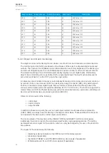
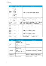
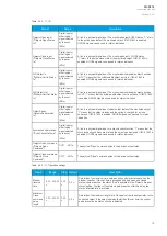
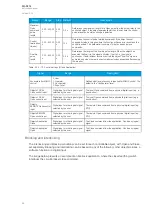
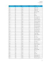
Event Number

Event channel

Event block name

Event Code

Description

9611

150

OBJ6

11

Open Command OFF

9612

150

OBJ6

12

Close Request ON

9613

150

OBJ6

13

Close Request OFF

9614

150

OBJ6

14

Close Command ON

9615

150

OBJ6

15

Close Command OFF

9616

150

OBJ6

16

Open Blocked ON

9617

150

OBJ6

17

Open Blocked OFF

9618

150

OBJ6

18

Close Blocked ON

9619

150

OBJ6

19

Close Blocked OFF

9620

150

OBJ6

20

Object Ready

9621

150

OBJ6

21

Object Not Ready

9622

150

OBJ6

22

Sync Ok

9623

150

OBJ6

23

Sync Not Ok

9624

150

OBJ6

24

Open Command Fail

9625

150

OBJ6

25

Close Command Fail

9626

150

OBJ6

26

Final trip ON

9627

150

OBJ6

27

Final trip OFF

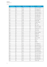
9664

151

OBJ7

0

Object Intermediate

9665

151

OBJ7

1

Object Open

9666

151

OBJ7

2

Object Close

9667

151

OBJ7

3

Object Bad

9668

151

OBJ7

4

WD Intermediate

9669

151

OBJ7

5

WD Out

9670

151

OBJ7

6

WD In

9671

151

OBJ7

7

WD Bad

9672

151

OBJ7

8

Open Request ON

9673

151

OBJ7

9

Open Request OFF

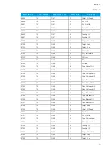
9674

151

OBJ7

10

Open Command ON

9675

151

OBJ7

11

Open Command OFF

9676

151

OBJ7

12

Close Request ON

9677

151

OBJ7

13

Close Request OFF

9678

151

OBJ7

14

Close Command ON

9679

151

OBJ7

15

Close Command OFF

9680

151

OBJ7

16

Open Blocked ON

9681

151

OBJ7

17

Open Blocked OFF

9682

151

OBJ7

18

Close Blocked ON

9683

151

OBJ7

19

Close Blocked OFF

9684

151

OBJ7

20

Object Ready

A

AQ

Q-S214

-S214

Instruction manual

Version: 2.04

65

Summary of Contents for AQ-S214

Page 1: ...AQ S214 Alarm and Indication IED Instruction manual ...

Page 2: ... Logical inputs 76 6 S 6 Sy yst stem int em integra egration tion 78 78 6 1 Communication protocols 78 6 1 1 NTP 78 6 1 2 Modbus TCP and Modbus RTU 79 6 1 3 Modbus I O 80 6 1 4 IEC 61850 80 6 1 5 GOOSE 82 6 1 6 IEC 103 82 6 1 7 DNP3 83 6 1 8 IEC 101 104 85 6 1 9 SPA 87 6 2 Analog fault registers 87 6 3 Real time measurements to communication 87 7 Connections and applic 7 Connections and applica at...

Page 3: ...l fiber communication module 115 9 1 2 5 Double LC 100 Mbps Ethernet communication module 115 9 1 3 Display 115 9 2 Functions 116 9 2 1 Control functions 116 9 2 1 1 Setting group selection 116 9 2 1 2 Object control and monitoring 116 9 2 2 Monitoring functions 116 9 3 Tests and environmental 116 10 Or 10 Ordering inf dering informa ormation tion 119 119 11 Contact and r 11 Contact and re ef fer ...

Page 4: ...y or extend the warranty obligations of the manufacturer Arcteq Relays Ltd The manufacturer expressly disclaims any and all liability for any damages and or losses caused due to a failure to comply with the instructions contained herein or caused by persons who do not fulfil the aforementioned requirements Furthermore the manufacturer shall not be liable for possible errors in this document Please...

Page 5: ...Copyright Copyright Arcteq Relays Ltd 2021 All rights reserved A AQ Q S214 S214 Instruction manual Version 2 04 4 ...

Page 6: ...xample drawing with function block diagram and application example with wiring Added General menu description Revision 2 01 Date 6 11 2019 Changes Added description for LED test and button test Complete rewrite of every chapter Improvements to many drawings and formula images Order codes revised Added double ST 100 Mbps Ethernet communication module and Double RJ45 10 100 Mbps Ethernet communicati...

Page 7: ...ions to Monitoring menu IED user interface chapter Added note to Configuring user levels and passwords chapter that user level with a password automatically locks itself after 30 minutes of inactivity Added more Tripped stage indications and fault types to Measurement value recorder function Updated Digital input activation and release threshold setting ranges and added drop off delay setting Revi...

Page 8: ...ated Revision 1 06 Date 13 3 2017 Changes Alarming function description revised CTRL button now clears all alarms Revision 1 07 Date 20 12 2017 Changes Event lists revised on several functions RTD mA card description improvements Ring lug CT card option description added Order code revised Revision 1 08 Date 18 1 2019 Changes Added HMI display technical data A AQ Q S214 S214 Instruction manual Ver...

Page 9: ...dule CTS Current transformer supervision DG Distributed generation DHCP Dynamic Host Configuration Protocol DI Digital input DO Digital output DOL Direct on line DR Disturbance recorder DT Definite time FF Fundamental frequency FFT Fast Fourier transform FTP File Transfer Protocol GI General interrogation HMI Human machine interface HR Holding register HV High voltage HW Hardware IDMT Inverse defi...

Page 10: ...ime Protocol RMS Root mean square RSTP Rapid Spanning Tree Protocol RTD Resistance temperature detector RTU Remote terminal unit SCADA Supervisory control and data acquisition SG Setting group SOTF Switch on to fault SW Software THD Total harmonic distortion TRMS True root mean square VT Voltage transformer VTM Voltage transformer module VTS Voltage transformer supervision A AQ Q S214 S214 Instruc...

Page 11: ...AQ S214 may be applied as a substation alarm sounder a substation general I O extension unit or in any other application that requires extended I O capabilities The local indications are visualized conveniently through the freely programmable alarm LED display and event list There are up to six 6 option card slots available for additional I O or communication cards for more comprehensive monitorin...

Page 12: ...nfigurable 2 Sixteen 16 freely configurable LEDs with programmable legend texts 3 Three 3 object control buttons Choose the controllable object with the Ctrl Ctrl button and control the breaker or other object with the I I and O O buttons 4 The L R L R button switches between the local and the remote control modes 5 Eight 8 buttons for IED local programming the four navigation arrows and the E Ent...

Page 13: ...ew might be different if you have changed the view with AQtivate s Carousel Designer tool Figure 4 2 1 2 Basic navigation for AQ S214 The Home Home button switches between the quick display carousel and the main display with the five 5 main configuration menus The AQ S214 alarm and indication IED has the following five configuration menus General Control Communication Transducers and Monitoring Yo...

Page 14: ...itoring They are presented in the image below Figure 4 2 2 3 Main configuration menus 4 3 General menu The General main menu is divided into two submenus the Device info tab presents the information of the device while the Function comments tab allows you to view all comments you have added to the functions Figure 4 3 4 General menu structure A AQ Q S214 S214 Instruction manual Version 2 04 13 ...

Page 15: ...nted on the sticker located on the side of the unit Time synchronization source 0 Internal 1 External NTP 2 External Serial 3 IRIG B 0 Internal If an external clock time synchronization source is available the type is defined with this parameter In the internal mode there is no external Timesync source IRIG B requires a serial fiber communication option card Enable stage forcing 0 Disabled 1 Enabl...

Page 16: ...eature is not in use LED test 0 1 Activated 0 When activated all LEDs are lit up LEDs with multiple possible colors blink each color Reset latches 0 1 Reset 0 Resets the latched signals in the logic and the matrix When a reset command is given the parameter automatically returns back to Measurement recorder 0 Disabled 1 Enabled 0 Disabled Enables the measurement recorder tool further configured in...

Page 17: ...the device in use Controls enabled Figure 4 4 7 Controls enabled submenu You can activate the selected control functions in the Controls enabled submenu By default all the control functions are disabled All activated functions can be viewed in the Control functions submenu see the section Control functions below for more information In this submenu you can also activate and disable controllable ob...

Page 18: ...al select al select selects the local control for the different setting groups can use digital inputs logical inputs or outputs RTDs object status information as well as stage starts trips or blocks R Remo emot te se e set tting gr ting group change oup change When enabled it is possible to change the setting group manually through SCADA SG e SG ev vents ents event masking for setting groups masks...

Page 19: ...nless specifically activated in the Controls Controls enabled submenu Each active object has four sections in their submenus Settings Application control App contr Registers and Events These are described in further detail below Figure 4 4 11 Settings section OBJECT SET AND STATUS A AQ Q S214 S214 Instruction manual Version 2 04 18 ...

Page 20: ... in SCADA Status can be indicated by any of the following digital inputs logical inputs or outputs A withdrawable object has both In In and Out Out inputs The status can be indicated by any of the following digital inputs logical inputs or outputs Both Ob Object r ject read eady y and S Synchr ynchrocheck permission ocheck permission have status inputs If either one is used the input s must be act...

Page 21: ...tput relays as well as to user configurable LEDs A connection to an output can be either latched x or non latched x Object blocking is done in the Blocking input control subsection It can be done by any of the following digital inputs logical inputs or outputs object status information as well as stage starts trips or blocks Figure 4 4 13 Registers section A AQ Q S214 S214 Instruction manual Versi...

Page 22: ...nts are masked off You can activate the desired events by masking them x Please remember to save your maskings by confirming the changes with the check mark icon If you want to cancel the changes select the strike through circle to do so Only masked events are recorded to the event history which can be accessed in the Events view in the user view section Control functions Once a control function h...

Page 23: ...nitored magnitude between Peak to peak TRMS or RMS the default is RMS the available magnitudes depend on the function Sta Statistics tistics indicates the number of function starts trips and blocks can be cleared through Clear statistics Clear Mea Measur surements ements displays the measurements carried out by the function A Activ ctive se e set ttings tings displays the setting group that is cur...

Page 24: ...ing tool Stored in the Registers section you can find both Operation event register and General event register Operation event register stores the function s specific operation data There are twelve 12 registers and each of them includes data like the pre fault value the fault value the time stamp and the active group during the trigger Data included in the register depend on the control function ...

Page 25: ...Ds If the stage is blocked internally by a digital input or another signal you can configure an output to indicate the stage that is blocked A connection to an output can be either latched x or non latched x Blocking input control allows you to block stages The blocking can be done by using any of the following digital inputs logical inputs or outputs the START TRIP or BLOCKED information of anoth...

Page 26: ...history which can be accessed in the Events view in the user view section Device I O Figure 4 4 21 Device I O submenu The Device I O submenu is divided into the following nine sections Digital inputs Digital outputs mA Outputs LED settings Device I O matrix Programmable control switch Programmable Mimic Indicator Logic signals and GOOSE matrix Please note that digital inputs logic outputs protecti...

Page 27: ...measured peak value The activation time of an input is 5 10 ms The release time with DC is 5 10 ms while with AC it is less than 25 ms The first three digital inputs don t have activation and release threshold voltage settings as these have already been defined when the unit was ordered Digital input statuses can be checked from the corresponding subsection Digital input status The Digital input d...

Page 28: ...ut output selection lists NO NOTE TE An NC signal goes to the default position NO if the relay loses the auxiliary voltage or if the system is fully reset However an NC signal does not open during voltage or during System full reset An NC output signal does not open during a Communication or Protection reset Figure 4 4 24 LED settings section The LED settings section allows you to modify the indiv...

Page 29: ...latched signal stays active until the triggering signal deactivates and the latched function is manually cleared You can clear latched signals by entering the mimic display and the pressing the Back Back button on the panel Figure 4 4 26 Programmable control switch section Programmable control switches PCSs are switches that can be used to control signals while in the mimic view These signals can ...

Page 30: ...0 or 1 64 GOOSE input signal status bits the status of a bit is either 0 or 1 64 quality bits for GOOSE input signals the status of a bit is either 0 or 1 Logical input signals can be used when building a logic with the AQtivate setting tool The status of a logical input signal can be changed either from the mimic or through SCADA By default logical inputs use Hold mode in which the status changes...

Page 31: ...tputs have both ON and OFF events and they can be masked on when necessary they are masked off by default NO NOTE TE Please refer to the System integration chapter for a more detailed description of the use of logical signals 4 5 Communication menu The Communication main menu includes four submenus Connections Protocols General IO and Realtime signals to Comm All devices can be configured through ...

Page 32: ...basic settings of RS 485 port in the back panel of the unit Bitrate displays the bitrate of the RS 485 serial communication interface 9600 bps as standard although can be changed to 19 200 bps or 38 400 bps if an external device supports the faster speed Databits Parity and Stopbits these can be set according the connected external devices Protocol by default the device does not have any serial pr...

Page 33: ...ocol Modbus RTU Serial communication protocol IEC103 Serial communication protocol IEC101 104 The standards IEC 60870 5 101 and IEC 60870 5 104 are closely related On the physical layer the IEC 101 protocol uses serial communication whereas the IEC 104 protocol uses Ethernet communication SPA Serial communication protocol DNP3 Supports serial and Ethernet communication ModbusIO Used for connecting...

Page 34: ...tivate the selected monitor functions in the Monitors enabled submenu By default all the control functions are disabled All activated functions can be viewed in the Monitor functions submenu see the section Monitor functions below for more information A AQ Q S214 S214 Instruction manual Version 2 04 33 ...

Page 35: ... present the events and registers Events and Registers Disturbance recorder Figure 4 6 34 Disturbance recorder settings The Disturbance recorder submenu has the following settings Recorder enabled enables or disables the recorder Recorder status indicates the status of the recorder Clear record records the chosen record in the memory Manual trigger triggers the recorder when set to Clear Goes back...

Page 36: ...s Recording mode can be selected to replace the oldest recording FIFO or to keep the old recordings FILO Analog channel samples determines the sample rate of analog channels and it can be selected to be 8 16 32 62 samples per cycle Digital channel samples displays the sample rate in a digital channel this is a fixed 5 ms Pretriggering time can be selected between 0 1 15 0 s The IED can record up t...

Page 37: ... 7 Configuring user levels and their passwords As a factory default no user level is locked with a password in an IED In order to activate the different user levels click the L Lock ock button in the device s HMI and set the desired passwords for the different user levels NO NOTE TE Passwords can only be set locally in an HMI A number of stars are displayed in the upper right corner of the HMI the...

Page 38: ...he required access level to change a parameter is indicated with a star symbol if such is required As a general rule the access levels are divided as follows User Can view any menus and settings but cannot change any settings nor operate breakers or other equipment Operator Can view any menus and settings but cannot change any settings BUT can operate breakers and other equipment Configurator Can ...

Page 39: ...NO NOTE TE Any user level with a password automatically locks itself after half an hour 30 minutes of inactivity A AQ Q S214 S214 Instruction manual Version 2 04 38 ...

Page 40: ... dynamic screen starts with an empty display and fills up the list as alarms are activated Switching between these modes can be done in the General menu Alarm descriptions Figure 5 1 36 User edited alarm descriptions The user edited alarm text is displayed in the Alarm view in the HMI when the alarm has been activated The user can update the descriptions in the settings Commands Write settings Ass...

Page 41: ...played with a blinking LED in the Alarms display If the alarm signal s ON state has been checked in the Event Mask an ALARM ON event is recorded with a time stamp into the event history These alarms are also reported in the communication protocol if one is in use Clearing activated alarms The user can clear all alarms by pressing the Ctrl Ctrl button located in the IED front panel Please note that...

Page 42: ...tivated the alarm text is still displayed but the LED will start blinking to indicate that the digital input is deactivated The first push of the Ctrl Ctrl button clears Alarm Text 1 and its corresponding LED Alarm Text 2 and its corresponding LED are not affected because Digital Input 2 is not yet deactivated By the time the Ctrl Ctrl button is pushed a second time Digital Input 2 is deactivated ...

Page 43: ...Matrix Whenever an alarm is activated the Alarm Buzzer signal will also activate and the output contact can be controlled The user can silence the alarm buzzer by pressing the Back Back button located in the IED panel or by connecting a digital input or some other binary signal in the logic to SILENCE ALARM BUZZER Clearing latched signals Figure 5 1 40 Latched signals as dots Latched signals are r...

Page 44: ... 8 ON 783 12 ALARM1 15 Alarm 8 OFF 784 12 ALARM1 16 Alarm 9 ON 785 12 ALARM1 17 Alarm 9 OFF 786 12 ALARM1 18 Alarm 10 ON 787 12 ALARM1 19 Alarm 10 OFF 788 12 ALARM1 20 Alarm 11 ON 789 12 ALARM1 21 Alarm 11 OFF 790 12 ALARM1 22 Alarm 12 ON 791 12 ALARM1 23 Alarm 12 OFF 792 12 ALARM1 24 Alarm 13 ON 793 12 ALARM1 25 Alarm 13 OFF 794 12 ALARM1 26 Alarm 14 ON 795 12 ALARM1 27 Alarm 14 OFF 796 12 ALARM1...

Page 45: ...12 ALARM1 52 Alarm 27 ON 821 12 ALARM1 53 Alarm 27 OFF 822 12 ALARM1 54 Alarm 28 ON 823 12 ALARM1 55 Alarm 28 OFF 824 12 ALARM1 56 Alarm 29 ON 825 12 ALARM1 57 Alarm 29 OFF 826 12 ALARM1 58 Alarm 30 ON 827 12 ALARM1 59 Alarm 30 OFF 828 12 ALARM1 60 Alarm 31 ON 829 12 ALARM1 61 Alarm 31 OFF 830 12 ALARM1 62 Alarm 32 ON 831 12 ALARM1 63 Alarm 32 OFF 832 13 ALARM2 0 Alarm 33 ON 833 13 ALARM2 1 Alarm ...

Page 46: ...ARM2 26 Alarm 46 ON 859 13 ALARM2 27 Alarm 46 OFF 860 13 ALARM2 28 Alarm 47 ON 861 13 ALARM2 29 Alarm 47 OFF 862 13 ALARM2 30 Alarm 48 ON 863 13 ALARM2 31 Alarm 48 OFF 864 13 ALARM2 32 Alarm 49 ON 865 13 ALARM2 33 Alarm 49 OFF 866 13 ALARM2 34 Alarm 50 ON 867 13 ALARM2 35 Alarm 50 OFF 868 13 ALARM2 36 Alarm 51 ON 869 13 ALARM2 37 Alarm 51 OFF 870 13 ALARM2 38 Alarm 52 ON 871 13 ALARM2 39 Alarm 52 ...

Page 47: ...ON 895 13 ALARM2 63 Alarm 64 OFF 5 2 Control functions 5 2 1 Setting group selection All relay types support up to eight 8 separate setting groups The Setting group selection function block controls the availability and selection of the setting groups By default only Setting group 1 SG1 is active and therefore the selection logic is idle When more than one setting group is enabled the setting grou...

Page 48: ...e Force SG change is disabled again Setting groups can be controlled either by pulses or by signal levels The setting group controller block gives setting groups priority values for situations when more than one setting group is controlled at the same time the request from a higher priority setting group is taken into use Setting groups follow a hierarchy in which setting group 1 has the highest p...

Page 49: ...ically controlled to ON after Force SG is disabled If there are no other controls the last set setting group remains active Force setting group change 0 Disabled 1 Enabled 0 Disabled The selection of whether the setting group forcing is enabled or disabled This setting has to be active before the setting group can be changed remotely or from a local HMI This parameter overrides the local control o...

Page 50: ... not be processed Setting group 6 0 Not active 1 Active 0 Not active The selection of Setting group 6 SG6 Has the third lowest priority input in setting group control Can be controlled with pulses or static signals If static signal control is applied SG7 and SG8 requests will not be processed Setting group 7 0 Not active 1 Active 0 Not active The selection of Setting group 7 SG7 Has the second low...

Page 51: ...itoring the state of the Petersen coil connection When the connection is done with one wire the setting group change logic can be applied as shown in the figure above The status of the Petersen coil controls whether Setting group 1 is active If the coil is disconnected Setting group 2 is active This way if the wire is broken for some reason the setting group is always controlled to SG2 A AQ Q S214...

Page 52: ...Figure 5 2 1 44 Setting group control two wire connection from Petersen coil status A AQ Q S214 S214 Instruction manual Version 2 04 51 ...

Page 53: ...itional logic With a two wire connection the state of the Petersen coil can be monitored more securely The additional logic ensures that a single wire loss will not affect the correct setting group selection The application controlled setting group change can also be applied entirely from the relay s internal logics For example the setting group change can be based on the cold load pick up functio...

Page 54: ...se of logics in setting group control One could also have SG2 be the primary SG while the ON signal would be controlled by the higher priority SG1 this way the setting group would automatically return to SG2 after the automatic control is over Events The setting group selection function block abbreviated SGS in event block names generates events from its controlling status its applied input signal...

Page 55: ...7 Request ON 4187 65 SGS 27 SG7 Request OFF 4188 65 SGS 28 SG8 Request ON 4189 65 SGS 29 SG8 Request OFF 4190 65 SGS 30 Remote Change SG Reqeuest ON 4191 65 SGS 31 Remote Change SG Request OFF 4192 65 SGS 32 Local Change SG Request ON 4193 65 SGS 33 Local Change SG Request OFF 4194 65 SGS 34 Force Change SG ON 4195 65 SGS 35 Force Change SG OFF 4196 65 SGS 36 SG Request Fail Not configured SG ON 4...

Page 56: ...control or by remote control Local manual control can be done by relays front panel HMI or by external push buttons connected to relays digital inputs Manual remote control can be done through one of the various communication protocols available Modbus IEC101 103 104 etc The function supports the modes Direct control and Select before execute while controlled remotely Automatic controlling can be ...

Page 57: ...ds while device is in Local status Object name Objectx The user set name of the object at maximum 32 characters long Object type 0 Withdrawable circuit breaker 1 Circuit breaker 2 Disconnector MC 3 Disconnector GND 1 Circuit breaker The selection of the object type This selection defines the number of required digital inputs for the monitored object This affects the symbol displayed in the HMI and...

Page 58: ...ests 0 232 1 1 Displays the number of successful Close requests Open requests failed 0 232 1 1 Displays the number of failed Open requests Close requests failed 0 232 1 1 Displays the number of failed Close requests Clear statistics 0 1 Clear 0 Clears the request statistics setting them back to zero 0 Automatically returns to after the clearing is finished Table 5 2 2 10 Object types Name Function...

Page 59: ...cted by the user SWx A link to a physical digital input Indicates that status of the monitored object 1 means that the object is ready and the spring is charged for a close command If IEC 61850 is enabled GOOSE signals can be used for status indication Syncrocheck permission Sync Check status In Digital input or other logical signal selected by the user SWx A link to a physical digital input or a ...

Page 60: ...bjectx LOCAL Close control input Digital input or other logical signal selected by the user The local Close command from a physical digital input e g a push button Objectx LOCAL Open control input Digital input or other logical signal selected by the user The local Open command from a physical digital input e g a push button Objectx REMOTE Close control input Digital input or other logical signal ...

Page 61: ...block names generates events and registers from the status changes in monitored signals as well as control command fails and operations The user can select which event messages are stored in the main event buffer ON OFF or both The function registers its operation into the last twelve 12 time stamped registers The events triggered by the function are recorded with a time stamp and with process dat...

Page 62: ...2958 46 OBJ1 14 Close Command ON 2959 46 OBJ1 15 Close Command OFF 2960 46 OBJ1 16 Open Blocked ON 2961 46 OBJ1 17 Open Blocked OFF 2962 46 OBJ1 18 Close Blocked ON 2963 46 OBJ1 19 Close Blocked OFF 2964 46 OBJ1 20 Object Ready 2965 46 OBJ1 21 Object Not Ready 2966 46 OBJ1 22 Sync Ok 2967 46 OBJ1 23 Sync Not Ok 2968 46 OBJ1 24 Open Command Fail 2969 46 OBJ1 25 Close Command Fail 2970 46 OBJ1 26 Fi...

Page 63: ... 47 OBJ2 24 Open Command Fail 3033 47 OBJ2 25 Close Command Fail 3034 47 OBJ2 26 Final trip ON 3035 47 OBJ2 27 Final trip OFF 3072 48 OBJ3 0 Object Intermediate 3073 48 OBJ3 1 Object Open 3074 48 OBJ3 2 Object Close 3075 48 OBJ3 3 Object Bad 3076 48 OBJ3 4 WD Intermediate 3077 48 OBJ3 5 WD Out 3078 48 OBJ3 6 WD In 3079 48 OBJ3 7 WD Bad 3080 48 OBJ3 8 Open Request ON 3081 48 OBJ3 9 Open Request OFF...

Page 64: ...49 OBJ4 7 WD Bad 3144 49 OBJ4 8 Open Request ON 3145 49 OBJ4 9 Open Request OFF 3146 49 OBJ4 10 Open Command ON 3147 49 OBJ4 11 Open Command OFF 3148 49 OBJ4 12 Close Request ON 3149 49 OBJ4 13 Close Request OFF 3150 49 OBJ4 14 Close Command ON 3151 49 OBJ4 15 Close Command OFF 3152 49 OBJ4 16 Open Blocked ON 3153 49 OBJ4 17 Open Blocked OFF 3154 49 OBJ4 18 Close Blocked ON 3155 49 OBJ4 19 Close B...

Page 65: ...n Blocked ON 3217 50 OBJ5 17 Open Blocked OFF 3218 50 OBJ5 18 Close Blocked ON 3219 50 OBJ5 19 Close Blocked OFF 3220 50 OBJ5 20 Object Ready 3221 50 OBJ5 21 Object Not Ready 3222 50 OBJ5 22 Sync Ok 3223 50 OBJ5 23 Sync Not Ok 3224 50 OBJ5 24 Open Command Fail 3225 50 OBJ5 25 Close Command Fail 3226 50 OBJ5 26 Final trip ON 3227 50 OBJ5 27 Final trip OFF 9600 150 OBJ6 0 Object Intermediate 9601 15...

Page 66: ...26 150 OBJ6 26 Final trip ON 9627 150 OBJ6 27 Final trip OFF 9664 151 OBJ7 0 Object Intermediate 9665 151 OBJ7 1 Object Open 9666 151 OBJ7 2 Object Close 9667 151 OBJ7 3 Object Bad 9668 151 OBJ7 4 WD Intermediate 9669 151 OBJ7 5 WD Out 9670 151 OBJ7 6 WD In 9671 151 OBJ7 7 WD Bad 9672 151 OBJ7 8 Open Request ON 9673 151 OBJ7 9 Open Request OFF 9674 151 OBJ7 10 Open Command ON 9675 151 OBJ7 11 Open...

Page 67: ...9 Open Request OFF 9738 152 OBJ8 10 Open Command ON 9739 152 OBJ8 11 Open Command OFF 9740 152 OBJ8 12 Close Request ON 9741 152 OBJ8 13 Close Request OFF 9742 152 OBJ8 14 Close Command ON 9743 152 OBJ8 15 Close Command OFF 9744 152 OBJ8 16 Open Blocked ON 9745 152 OBJ8 17 Open Blocked OFF 9746 152 OBJ8 18 Close Blocked ON 9747 152 OBJ8 19 Close Blocked OFF 9748 152 OBJ8 20 Object Ready 9749 152 O...

Page 68: ...ose Blocked ON 9811 153 OBJ9 19 Close Blocked OFF 9812 153 OBJ9 20 Object Ready 9813 153 OBJ9 21 Object Not Ready 9814 153 OBJ9 22 Sync Ok 9815 153 OBJ9 23 Sync Not Ok 9816 153 OBJ9 24 Open Command Fail 9817 153 OBJ9 25 Close Command Fail 9818 153 OBJ9 26 Final trip ON 9819 153 OBJ9 27 Final trip OFF 9856 154 OBJ10 0 Object Intermediate 9857 154 OBJ10 1 Object Open 9858 154 OBJ10 2 Object Close 98...

Page 69: ... Object status The status of the object WD status The status of the withdrawable circuit breaker Open fail The cause of an Open command s failure Close fail The cause of a Close command s failure Open command The source of an Open command Close command The source of an Open command General status The general status of the function 5 2 3 Indicator object monitoring The indicator object monitoring f...

Page 70: ...nd close are active Table 5 2 3 17 Indicator I O Signal Range Description IndicatorX Open input Ind X Open Status In Digital input or other logical signal selected by the user SWx A link to a physical digital input The monitored indicator s OPEN status 1 refers to the active Open state of the monitored indicator If IEC 61850 is enabled GOOSE signals can be used for status indication IndicatorX Clo...

Page 71: ...tive The benefits of 4 20 mA loops the dominant standard in many industries the simplest option to connect and configure uses less wiring and connections than other signals thus greatly reducing initial setup costs good for travelling long distances as current does not degrade over long connections like voltage does less sensitive to background electrical noise detects a fault in the system incred...

Page 72: ...d admittance 4 Other 0 Currents Defines the measurement category that is used for mA output control Magnitude of mA output channel dependent on the measurement category selection dependent on the measurement category selection Defines the measurement magnitude used for mA output control The available measurements depend on the selection of the Magnitude selection for mA output channel parameter In...

Page 73: ...as a box in the mimic or remotely from the RTU The main purpose of programmable control switches is to block or enable function and to change function properties by changing the setting group However this binary signal can also be used for any number of other purposes just like all other binary signals Once a programmable control switch has been activated or disabled it remains in that state until...

Page 74: ... from the source is inaccurate One common example of this is tap changer location indication signal not changing linearly from step to step If the output difference between the steps are not equal to each other measuring the incoming signal accurately is not enough Analog input scaling curves menu can be used to take these inaccuracies into account Analog input scaling curve settings can be found ...

Page 75: ...mum 1 000 000 00 1 000 000 00 0 00001 0 Defines the minimum input of the curve If input is below the set limit ASC1 4 input out of range is activated Curve 1 4 input 1 000 000 00 1 000 000 00 0 00001 Displays the input measurement received by the curve Curve1 4 input maximum 1 000 000 00 1 000 000 00 0 00001 0 Defines the maximum input of the curve If input is above the set limit ASC1 4 input out ...

Page 76: ...ations Name Range Step Default Description Curve 1 4 update cycle 5 10 000ms 5ms 150ms Defines the length of the input measurement update cycle If the user wants a fast operation this setting should be fairly low Scaled value handling 0 Floating point 1 Integer out Floor 2 Integer Ceiling 3 Integer Nearest 0 Floating point Rounds the milliampere signal output as selected Input value 1 0 4000 0 000...

Page 77: ...y to change the behavior of the AQ 200 unit or to give direct control commands Logical inputs can be controlled with a virtual switch built in the mimic and from a SCADA system IEC 61850 Modbus IEC 101 etc Logical inputs are volatile signals their status will always return to 0 when the AQ 200 device is rebooted Logical inputs have two modes available Hold and Pulse When a logical input which has ...

Page 78: ...lse can also be extended by connecting a DELAY low gate to a logical output as has been done in the example figure below Figure 5 2 8 53 Extending a logical input pulse A AQ Q S214 S214 Instruction manual Version 2 04 77 ...

Page 79: ... 0 255 255 255 255 Defines the address of the NTP client NO NOTE TE This address must be different than the relay s IP address Netmask 0 0 0 0 255 255 255 255 Defines the client s netmask Gateway 0 0 0 0 255 255 255 255 Defines the client s gateway MAC address Displays the MAC address of the client Network status 0 Running 1 IP error 2 NM error 3 GW error Displays the status or possible errors of ...

Page 80: ...d 1 Enabled Enables and disables the Modbus TCP on the Ethernet port IP port 0 65 535 Defines the IP port used by Modbus TCP The standard port and the default setting is 502 Event read mode 0 Get oldest available 1 Continue previous connection 2 New events only 0 Get oldest event possible Default and current implementation 1 Continue with the event idx from previous connection 2 Get only new event...

Page 81: ... Channel 7 or None Selects the number of channels to be used by the module Table 6 1 3 34 Channel settings Name Range Step Default Description T C type 0 20mA 1 4 20mA 2 Type J 3 Type K 4 Type T 5 Type E 6 Type R 7 Type S 1 4 20mA Selects the thermocouple or the mA input connected to the I O module Types J K T and E are nickel alloy thermocouples while Types R and S are platinum rhodium alloy ther...

Page 82: ...easurement Apparent power deadband 0 1 1000 0kVA 0 1kVA 2kVA Determines the data reporting deadband settings for this measurement Power factor deadband 0 01 0 99 0 01 0 05 Determines the data reporting deadband settings for this measurement Frequency deadband 0 01 1 00Hz 0 01Hz 0 1Hz Determines the data reporting deadband settings for this measurement Current deadband 0 01 50 00A 0 01A 5A Determin...

Page 83: ...Rev 1 232 1 1 1 Defines the configuration revision that will be matched with the publisher s GOOSE control block Data index DataIdx 0 99 1 Defines the data index of the value in the matched published frame It is the status of the GOOSE input NextIdx is quality 0 No 1 Yes 0 No Selects whether or not the next received input is the quality bit of the GOOSE input Data type 0 Boolean 1 Integer 2 Unsign...

Page 84: ... Communication DNP3 IP port 0 65 535 1 20 000 Defines the IP port used by the protocol Slave address 1 65 519 1 1 Defines the DNP3 slave address of the unit Master address 1 65 534 1 2 Defines the address for the allowed master Link layer time out 0 60 000ms 1ms 0ms Defines the length of the time out for the link layer Link layer retries 1 20 1 1 Defines the number of retries for the link layer Di...

Page 85: ...r deadband 0 1 1000 0kW 0 1kW 2kW Determines the data reporting deadband settings for this measurement Reactive power deadband 0 1 1000 0kVar 0 1kVar 2kVar Determines the data reporting deadband settings for this measurement Apparent power deadband 0 1 1000 0kVA 0 1kVA 2kVA Determines the data reporting deadband settings for this measurement Power factor deadband 0 01 0 99 0 01 0 05 Determines the...

Page 86: ...yer address 0 65 534 1 1 Defines the address for the link layer Link layer address size 1 2 1 2 Defines the address size of the link layer Information object address size 2 3 1 3 Defines the address size of the information object Cause of transmission size 1 2 1 2 Defines the cause of transmission size IEC 104 settings Table 6 1 8 41 IEC 104 settings Name Range Step Default Description IEC 104 ena...

Page 87: ...d settings for this measurement Apparent power deadband 0 1 1000 0kVA 0 1kVA 2kVA Determines the data reporting deadband settings for this measurement Power factor deadband 0 01 0 99 0 01 0 05 Determines the data reporting deadband settings for this measurement Frequency deadband 0 01 1 00Hz 0 01Hz 0 1Hz Determines the data reporting deadband settings for this measurement Current deadband 0 01 50 ...

Page 88: ...me menu or through a communication protocol if one is in use The following table presents the setting parameters available for the 12 channels Table 6 2 43 Fault register settings Name Range Step Default Description Select record source 0 Not in use 1 12 I I I I IL1 IL2 IL3 13 24 Id Id Id Id IL1 IL2 IL3 25 28 I0 I0 I0 I0 I0 29 32 I0d I0d I0d I0d I0 33 FLX 0 Not in use Selects the protection functi...

Page 89: ...ce current I0CalcMag Residual current calculated from phase currents IL1Ang IL2Ang IL3Ang I01Ang I02Ang I0CalcAng I1Ang I2Ang Angles of each measured current Voltages UL1Mag UL2Mag UL3Mag UL12Mag UL23Mag UL31Mag U0Mag U0CalcMag Magnitudes of phase voltages phase to phase voltages and residual voltages U1 Pos seq V mag U2 Neg seq V mag Positive and negative sequence voltages UL1Ang UL2Ang UL3Ang UL...

Page 90: ...ment channels 1 8 ADAM module Settings Table 6 3 45 Settings Name Range Step Default Description Measurement value recorder mode 0 Disabled 1 Activated 0 Disabled Activates and disables the real time signals to communication Scale current values to primary 0 No 1 Yes 0 No Selects whether or not values are scaled to primary Slot X magnitude selection 0 Currents 1 Voltages 2 Powers 3 Impedance ZRX a...

Page 91: ...7 Connections and application examples 7 1 Connections of AQ S214 Figure 7 1 54 AQ S214 variant without add on modules A AQ Q S214 S214 Instruction manual Version 2 04 90 ...

Page 92: ...Figure 7 1 55 AQ S214 variant with digital input and output modules A AQ Q S214 S214 Instruction manual Version 2 04 91 ...

Page 93: ...Figure 7 1 56 AQ S214 application example A AQ Q S214 S214 Instruction manual Version 2 04 92 ...

Page 94: ... digital I O modules or a special module The only difference between the slots affecting device scalability is that Slots E and F also support communication options When an add on module is inserted into the device the start up scan searches for modules according to their type designation code If the module location or content is not what the device expects the IED does not take additional modules...

Page 95: ...an The start up system detects and self tests the CPU module voltages communication and the I O finds and assigns DI1 DI2 DI3 OUT1 OUT2 OUT3 OUT4 and OUT5 2 Scan Scans Slot A and moves to the next slot if Slot A is empty If the scan finds an 8DI module that is a module with eight digital inputs it reserves the designations DI4 DI5 DI6 DI7 DI8 DI9 DI10 and DI11 to this slot If the scan finds a DO5 ...

Page 96: ...rs the new ones accordingly 7 Scan A similar operation to Scan 3 checks which designations have been reserved by modules in previous slots and numbers the new ones accordingly Thus far this document has only explained the installation of I O add on cards to the option module slots This is because all other module types are treated in a same way For example when an additional communication port is ...

Page 97: ...igital inputs Model with 2 digital inputs Model with 2 digital inputs X 1 Digital input 1 nominal threshold voltage 24 V 110 V or 220 V Digital input 1 nominal threshold voltage 24 V 110 V or 220 V X 2 Digital input 2 nominal threshold voltage 24 V 110 V or 220 V GND for digital input 1 X 3 Digital input 3 nominal threshold voltage 24 V 110 V or 220 V Digital input 2 nominal threshold voltage 24 V...

Page 98: ...echnical data section of this document Digital input settings The settings described in the table below can be found at Control Device I O Digital input settings in the relay settings Table 8 2 47 Digital input settings Name Range Step Default Description DIx Polarity 0 NO Normally open 1 NC Normally closed 0 NO Selects whether the status of the digital input is 1 or 0 when the input is energized ...

Page 99: ...s original installation when required The properties of the inputs in this module are the same as those of the inputs in the main processor module The current consumption of the digital inputs is 2 mA when activated while the range of the operating voltage is from 0 265 VAC DC The activation and release thresholds are set in the software and the resolution is 1 V All digital inputs are scannced in...

Page 100: ...lay 0 000 1800 000 s 0 001 s 0 000 s Defines the delay when the status changes from 0 to 1 DIx Drop off time 0 000 1800 000 s 0 001 s 0 000 s Defines the delay when the status changes from 1 to 0 DIx AC Mode 0 Disabled 1 Enabled 0 Disabled Selects whether or not a 30 ms deactivation delay is added to take the alternating current into account The DIx Release threshold parameter is hidden and forced...

Page 101: ...gital inputs Digital input voltages Table 8 3 49 Digital input channel voltage measurement Name Range Step Description DIx Voltage now 0 000 275 000 V 0 001 V Voltage measurement of a digital input channel 8 4 Digital output module optional Figure 8 4 62 Digital output module DO5 with five add on digital outputs Connector Description X 1 2 OUTx 1 1st and 2nd pole NO X 3 4 OUTx 2 1st and 2nd pole N...

Page 102: ...C outputs is 250 VAC DC For the naming convention of the digital inputs provided by this module please refer to the chapter titled Construction and installation For technical details please refer to the chapter titled Digital output module in the Technical data section of this document 8 5 RTD input module optional Figure 8 5 63 RTD input module connectors The RTD input module is an add on module ...

Page 103: ...8 6 65 Serial RS 232 module connectors Connector Name Description COM E Serial fiber GG PP GP PG Serial based communications Wavelength 660 nm Compatible with 50 125 μm 62 5 125 μm 100 140 μm and 200 μm Plastic Clad Silica PCS fiber Compatible with ST connectors A AQ Q S214 S214 Instruction manual Version 2 04 102 ...

Page 104: ... 232 TX Serial based communications COM F Pin 8 RS 232 RX Serial based communications COM F Pin 9 COM F Pin 10 3 3 V output spare Spare power source for external equipment 45 mA COM F Pin 11 COM F Pin 12 The option card includes two serial communication interfaces COM E is a serial fiber interface with glass plastic option COM F is an RS 232 interface 8 7 LC 100 Mbps Ethernet communication module ...

Page 105: ...ocols The card has two PRP HSR ports which are 100 Mbps fiber ports 8 8 Double ST 100 Mbps Ethernet communication module optional Figure 8 8 67 Double ST 100 Mbps Ethernet communication module connectors Connector Description Two pin connector IRIG B input ST connectors Duplex ST connectors IRIG B input 62 5 125 μm or 50 125 μm multimode fiber Transmitter wavelength 1260 1360 nm nominal 1310 nm Re...

Page 106: ...y third party devices must be connected to a separate ring For other redundancy options please refer to the option card LC 100 Mbps Ethernet communication module The images below present two example configurations the first displays a ring configuration note how the third party devices are connected in a separate ring while the second displays a multidrop configuration Figure 8 8 68 Example of a r...

Page 107: ...tion 8 9 Double RJ 45 10 100 Mbps Ethernet communication module optional Figure 8 9 70 Double RJ 45 10 100 Mbps Ethernet communication module Connector Description Two pin connector IRIG B input A AQ Q S214 S214 Instruction manual Version 2 04 106 ...

Page 108: ...lease refer to the option card LC 100 Mbps Ethernet communication module The images below present two example configurations the first displays a ring configuration note how the third party devices are connected in a separate ring while the second displays a multidrop configuration Figure 8 9 71 Example of a ring configuration A AQ Q S214 S214 Instruction manual Version 2 04 107 ...

Page 109: ...d in the order code When installing to a rack the device takes a quarter of the rack s width meaning that a total of four devices can be installed to the same rack next to one another The figures below describe the device dimensions first figure the device installation second and the panel cutout dimensions and device spacing third Figure 8 10 73 Device dimensions A AQ Q S214 S214 Instruction manu...

Page 110: ...Figure 8 10 74 Device installation A AQ Q S214 S214 Instruction manual Version 2 04 109 ...

Page 111: ...Figure 8 10 75 Panel cutout dimensions and device spacing A AQ Q S214 S214 Instruction manual Version 2 04 110 ...

Page 112: ...imum wire diameter 2 5 mm2 Table 9 1 1 1 51 Power supply model B Rated values Rated auxiliary voltage 18 72 VDC Power consumption 7 W 15 W Maximum permitted interrupt time 90 ms with 24 VDC DC ripple 15 Terminal block connection Terminal block Phoenix Contact MSTB 2 5 5 ST 5 08 Solid or stranded wire Maximum wire diameter 2 5 mm2 9 1 1 2 CPU communication ports Table 9 1 1 2 52 Front panel local c...

Page 113: ...r panel system communication port B Port Port media Copper RS 485 Number of ports 1 Features Port protocols Modbus RTU IEC 103 IEC 101 DNP3 SPA Data transfer rate 65 580 kB s System integration Can be used for system protocols 9 1 1 3 CPU digital inputs Table 9 1 1 3 55 CPU model isolated digital inputs with thresholds defined by order code Rated values Rated auxiliary voltage 265 V AC DC Nominal ...

Page 114: ...A Control rate 5 ms Settings Polarity Software settable Normally On Normally Off Terminal block connection Terminal block Phoenix Contact MSTB 2 5 5 ST 5 08 Solid or stranded wire Maximum wire diameter 2 5 mm2 Table 9 1 1 4 57 Digital outputs Change Over Rated values Rated auxiliary voltage 265 V AC DC Continuous carry 5 A Make and carry 0 5 s Make and carry 3 s 30 A 15 A Breaking capacity DC L R ...

Page 115: ...ock Phoenix Contact MSTB 2 5 5 ST 5 08 Solid or stranded wire Maximum wire diameter 2 5 mm2 9 1 2 2 Digital output module Table 9 1 2 2 59 Technical data for the digital output module Rated values Rated auxiliary voltage 265 V AC DC Continuous carry 5 A Make and carry 0 5 s Make and carry 3 s 30 A 15 A Breaking capacity DC L R 40 ms at 48 VDC at 110 VDC at 220 VDC 1 A 0 4 A 0 2 A Control rate 5 ms...

Page 116: ...LC 100 Mbps Ethernet communication module Table 9 1 2 5 62 Technical data for the double LC 100 Mbps Ethernet communication module Protocols Protocols HSR and PRP Ports Quantity of fiber ports 2 Communication port C D LC fiber connector Wavelength 1300 nm Fiber cable 50 125 μm or 62 5 125 μm multimode glass 9 1 3 Display Table 9 1 3 63 Technical data for the HMI LCD display Dimensions and resoluti...

Page 117: ...control and monitoring function Signals Input signals Digital inputs Software signals Output signals Close command output Open command output Operation time Breaker traverse time setting 0 02 500 00 s setting step 0 02 s Max close open command pulse length 0 02 500 00 s setting step 0 02 s Control termination time out setting 0 02 500 00 s setting step 0 02 s Inaccuracy Definite time operating tim...

Page 118: ... IEC 61000 4 6 f 150 kHz 80 MHz 10 V RMS Table 9 3 67 Voltage tests Dielectric voltage test EN 60255 27 IEC 60255 5 EN 60255 1 2 kV AC 50 Hz 1 min Impulse voltage test EN 60255 27 IEC 60255 5 5 kV 1 2 50 µs 0 5 J Physical environment compatibility Table 9 3 68 Mechanical tests Vibration test EN 60255 1 EN 60255 27 IEC 60255 21 1 Class 1 2 13 2 Hz 3 5 mm 13 2 100 Hz 1 0 g Shock and bump test EN 602...

Page 119: ...re range 40 70 C Other Altitude 2000 m Overvoltage category III Pollution degree 2 Casing and package Table 9 3 71 Dimensions and weight Without packaging net Dimensions Height 117 mm 4U Width 127 mm rack Depth 174 mm no cards connectors Weight 1 5 kg With packaging gross Dimensions Height 170 mm Width 242 mm Depth 219 mm Weight 2 kg A AQ Q S214 S214 Instruction manual Version 2 04 118 ...

Page 120: ...ctur urer er ADAM 4015 CE External 6 channel 2 or 3 wires RTD Input module pre configured Requires an external power module Advanced Co Ltd ADAM 4018 BE External 8 ch Thermocouple mA Input module pre configured Requires an external power module Advanced Co Ltd A AQ Q S214 S214 Instruction manual Version 2 04 119 ...

Page 121: ...AQX033 Raising frame 87 mm Arcteq Ltd AQX070 Raising frame 40 mm Arcteq Ltd AQX069 Combiflex frame Arcteq Ltd AQX097 Wall mounting bracket Arcteq Ltd A AQ Q S214 S214 Instruction manual Version 2 04 120 ...

Page 122: ... Visiting and postal address Kvartsikatu 2 A 1 65300 Vaasa Finland Contacts Phone 358 10 3221 370 Fax 358 10 3221 389 Website general arcteq fi Website technical support support arcteq fi E mail sales sales arcteq fi A AQ Q S214 S214 Instruction manual Version 2 04 121 ...

Reviews: