FFLB User Manual 200214 Page 6 of 8
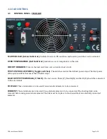
3.2 CONTROL PANEL - FFLB3KW & FFLB5KW
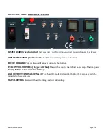
MASTER LOAD
(Green Indicator)
: Indicates load is in ON condition and load step switches can be activated
OVER TEMPERATURE
(Red Indicator)
: Indicates an over temperature in the Unit.
CIRCUIT BREAKER
: Protects load unit from over current & short circuit.
STEP CONTROL SWITCHES
(Toggle switches)
: The switches control the defined power steps. The total power
of the system will be sum of the activated steps.
LOAD OUTPUT TERMINALS (P, N & E)
:
The Phase (P), Neutral (N) and Earth (E) of the test source are to be
connected to these terminals
DIGITAL METERS
:
Meters will show the voltage and current readings.


