FFLB User Manual 200214 Page 5 of 8
3. LOAD CONTROL
3.1
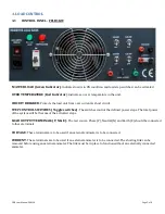
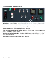
CONTROL PANEL - FFLB1KW
MASTER LOAD
(Green Indicator)
: Indicates load is in ON condition and load step switches can be activated
OVER TEMPERATURE
(
Red Indicator
)
: Indicates an over temperature in the unit.
CIRCUIT BREAKER
: Protects the load unit from over current & short circuit.
STEP CONTROL SWITCHES
(Toggle switches)
: The switches control the defined power steps. The total power
of the system will be the sum of the activated steps.
LOAD OUTPUT TERMINALS (P, N & E)
:
The test source, Phase (P), Neutral (N) and Earth (E) should be connected
to these terminals
VOLTAGE
: These terminals are to be used if an external voltmeter is to be connected.
CURRENT
: These terminals are to be used if an external ammeter is to be connected. The shorting link can be
removed before using an external ammeter. The link must be in place to function without an externally connected
ammeter.


