background image

21

*NC17

  Greece

*NC10 

 Netherlands

*NC7 

 Ireland

*NC8 

 Italy

*NC43

  Japan

*NC26 

 Namibia

*NC11 

 Norway

*NC12 

 Portugal

*NC27 

 South Africa

*NC13

  Spain

*NC14

  Sweden

*NC15

  Switzerland

*NC16

  UK

*NC19

  Czech Republic

*NC24 

 Poland

*NC25 

 Russia

*NC22

  United States

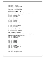
*Tn Trellis Coding Selection

*T0  

Disables Trellis coding

*T1*

  Enables Trellis coding

*On Transmission Level Selection

*O0*  

Selects output level -11dBm

*O1

  Selects output level -12dBm

*O2

  Selects output level -13dBm

*O3

  Selects output level -14dBm

*O4

  Selects output level -15dBm

*O5

  Selects output level -16dBm

*O6

  Selects output level -17dBm

*O7

  Selects output level -18dBm

*O8 

 Selects output level -19dBm

*O9

  Selects output level -20dBm

*O10

  Selects output level -21dBm

*O11

  Selects output level -22dBm

*O12

  Selects output level -23dBm

*O13

  Selects output level -24dBm

*O14

  Selects output level -25dBm

*O15

  Selects output level -26dBm

Summary of Contents for 5634PCV

Page 1: ...1 5634 PCV User s Manual ...

Page 2: ...necting to your telephone 5 1 7 Verifying your connection 6 1 8 Windows 95 98 Modem Driver Installation PnP 7 1 9 Windows NT4 0 Modem Driver Installation 8 1 10 Linux Red Hat 6 0 Modem Driver Installation 8 1 11 MS DOS Modem Driver Installation 9 Chapter 2 AT commands set 11 2 1 Data Mode Command 11 2 2 Result Code 23 2 3 S Registers Definitions 25 2 4 Class 1 Fax Commands 32 2 5 Voice Commands 35...

Page 3: ...ur dealer immediately 1 2 Installing the modem The following instructions explain how to install the modem in a IBM compatible type personal computer If you will be installing the modem into a different computer refer to the manual that accompanied your computer or contact your computer dealer for instructions on installing the modem in your personal computer 1 3 Removing the computer cover Turn o...

Page 4: ...he slot cover if you decide to remove the internal modem in the future 4 Hold the internal modem above the slot you selected making sure the modem s edge connectors are pointing down toward the base of the personal computer see Figure1 1 5 Carefully slide the modem into the PCI slot applying even pressure to both ends of the modem Stop inserting the modem when its gold plated edge connectors are a...

Page 5: ...ular telephone cable supplied with the modem and plug it into the LINE modular telephone jack on the back of the modem see Figure 1 2 4 Plug the other end of the telephone cord into the telephone jack on the wall as you would any modular telephone 1 6 Connecting to your telephone Your modem is so convenient it provides a second modular telephone jack that lets you connect your telephone to the sam...

Page 6: ...dem installation If you connected the modem to a computer place the computer into terminal mode and complete the configuration information required by the software Refer to your computer manual to find out the appropriate command to use Then use the following procedure to verify that your connections 1 Type AT and press the Enter key If your system is operating properly your modem sends an OK resp...

Page 7: ...dem speaker because the modem is calling itself Your modem is now ready for operation Refer to the manual that came with your communication software to begin communications If you will be communicating directly with your modem or if you want to find out more about the modem s operation proceed to Chapter 2 1 8 Windows95 98 ModemDriver Installation PNP 1 Install the PnP modem into an available slot...

Page 8: ...sert Setup program for Windows NT drivers disk into drive A or B 3 Execute the Setup program to install the PCI agent driver 4 Then after the installation is completed reboot PC 5 After PC is rebooted and NT is running follow the steps described in section 1 1 to add the modem and its drivers NOTE Microsoft does not support plug and play in Windows NT 4 0 1 10 Linux Red Hat 6 0 Modem Driver Instal...

Page 9: ...stallation Introduction This program intends to provide the function for hardware resource configuration via 5634PCV internal modem card It is only can be executed in DOS environment Windows DOS prompt is inhabited to run this program Installation Prior launching the program 5634PCV PCI modem card must be installed in the PC in advance Besides it can be used to configure the multiple PCI cards Con...

Page 10: ... the command to UART of PCI card the program will first verify the IO and interrupt setting If the verification is failed it will stop the diagnosis and prompt a waning message to the screen After the diagnosis is done it will show the PCI information including device ID vendor ID subsystem ID and subsystem vendor ID Moreover the version number and built date of modem controller and DSP code will ...

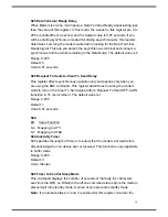
Page 11: ...h a response in either text or numeric values known as result codes In the following all commands command values and result code recognized by the modem are shown any entries other than those shown cause the ERROR result code The modem accepts either upper or lower case characters in the command line and ignores any spaces within or between commands Typing errors can be corrected with the Backspac...

Page 12: ...ling default W Wait for second dial tone Wait for quiet answer Wait for five seconds of silence after dialing the number Hook flash Pause during dialing Return to command mode Disable data calling tone transmission S n Dial a telephone number previously stored using the Zn x command see the Zn x command for further information The range of n is 0 En Echo Command ATEn command controls whether or no...

Page 13: ...ion for application software identification TP560 Data Fax Voice 56K Modem I4 Returns firmware version for data pump I5 Returns country code I6 Return Local Phone Status Loop Current Detection 0 On hook 1 Off hook Result Codes n 0 1 2 3 4 5 6 ERROR Otherwise Ln Monitor Speaker Volume This command sets speaker volume to low medium or high L0 Select low volume L1 Select low volume L2 Select medium v...

Page 14: ...hen originating or answering this is for handshake only at the communication standard specified by AT Nn N1 During handshake Highest speed is specified by AT Nn Depend on line quality fallback to a lower speed may occur Result Codes OK n 0 1 ERROR Otherwise On Return Online to Data Mode O0 Exit online command mode and return to data mode see AT Escape Sequence AT O1 This command issues a retrain b...

Page 15: ...lt codes as numeric V1 Displays result codes as text Result Codes OK n 0 1 ERROR Otherwise Wn Result Code Option W0 Display CONNECT DCE speed without V42 MNP extended W1 Display CONNECT DTE speed without V42 MNP extended W2 Display CONNECT DCE speed with V42 MNP extended W3 Display CONNECT DTE speed with V42 MNP extended Result Codes OK n 0 1 2 ERROR Otherwise Xn Result Code Selection and Call Pro...

Page 16: ...cts the carrier signal C0 The state of the carrier from the remote modem is ignored DCD circuit is always on C1 DCD turns on when the remote modem s carrier signal is detected and off when the carrier signal is not detected Result Codes OK n 0 1 ERROR Otherwise Dn DTR Control Data Terminal Ready This command interprets how the modem responds to the state of the DTR signal and changes to the DTR si...

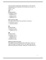
Page 17: ...nternational use only G0 Guard tone disabled G1 Sets guard tone to 550 Hz G2 Sets guard tone to 1800 Hz Result Codes OK n 0 1 2 ERROR Otherwise Kn Local Flow Control Selection K0 Disable flow control K1 Reserved K2 Reserved K3 Enable RTS CTS flow control K4 Enable XON XOFF flow control K5 Enable Transparent XON XOFF flow control Result Codes OK n 0 1 2 3 4 ERROR Otherwise Pn Pulse Dial Make to Bre...

Page 18: ...otocol Selection U0 Select V PCM U1 Select V 34Bis V 34 U2 Select V 32Bis V 22Bis U3 Select Bell 103 300bps U4 Select V21 300bps U5 Select V23 V View Active Configuration and Stored Profile This command is used to display the active profiles Wn Store Current Configuration This command stores certain command options and S register values into the modem nonvolatile memory The ATZ command or a power ...

Page 19: ...tain up to 31 characters The ATDS n command dials using the string stored in location n Result Codes OK n 0 1 2 ERROR Otherwise In Connect Speed Selection I0 Selects connect speed 1200bps I1 Selects connect speed 2400bps I2 Selects connect speed 4800bps I3 Selects connect speed 7200bps I4 Selects connect speed 9600bps I5 Selects connect speed 12000bps I6 Selects connect speed 14400bps I7 Selects c...

Page 20: ...15 Selects connect speed 46666bps I16 Selects connect speed 48000bps I17 Selects connect speed 49333bps I18 Selects connect speed 50666bps I19 Selects connect speed 52000ps I20 Selects connect speed 53333bps I21 Selects connect speed 54666bps I22 Selects connect speed 56000bps Gn User Abort Selection G0 Enables user abort feature G1 Disables user abort feature Hn Auto Retrain Selection H0 Disables...

Page 21: ...n Transmission Level Selection O0 Selects output level 11dBm O1 Selects output level 12dBm O2 Selects output level 13dBm O3 Selects output level 14dBm O4 Selects output level 15dBm O5 Selects output level 16dBm O6 Selects output level 17dBm O7 Selects output level 18dBm O8 Selects output level 19dBm O9 Selects output level 20dBm O10 Selects output level 21dBm O11 Selects output level 22dBm O12 Sel...

Page 22: ...dem attempts to connect in MNP mode If this fails the modem connects in buffer mode and continues operation This is also known as V 42 MNP auto reliable mode N6 V 42 or disconnect The modem attempts to connect in V 42 error control mode If this fails the call will be disconnected N7 V 42 MNP or buffer default Result Codes OK n 0 1 2 3 4 5 6 ERROR Otherwise Vn Protocol Result Code V0 Disable protoc...

Page 23: ...x x CONNECT 9600 12 x x x x CONNECT 7200 13 x x x x CONNECT 12000 14 x x x x CONNECT 14400 20 x x x x CONNECT 19200 21 x x x x CONNECT 38400 22 x x x x CONNECT 57600 23 x x x x CONNECT 115200 24 x x x x CONNECT 1200TX 75RX 25 x x x x CONNECT 75TX 1200RX 26 x x x x RINGBACK 27 x x x x CONNECT BELL 300 28 x x x x CONNECT V21 29 x x x x Display DCE speeds by ATW0 and ATW2 CONNECT 16800 15 x x x x CON...

Page 24: ...CT 34666 39 x x x x CONNECT 36000 40 x x x x CONNECT 37333 41 x x x x CONNECT 38666 42 x x x x CONNECT 40000 43 x x x x CONNECT 41333 44 x x x x CONNECT 42666 45 x x x x CONNECT 44000 46 x x x x CONNECT 45333 47 x x x x CONNECT 46666 48 x x x x CONNECT 48000 49 x x x x CONNECT 49333 50 x x x x CONNECT 50666 51 x x x x CONNECT 52000 52 x x x x CONNECT 53333 53 x x x x CONNECT 54666 54 x x x x CONNE...

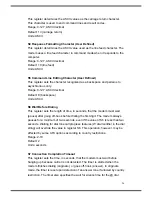
Page 25: ... a call 0 zero is that asks modem don t do automatically answer at all When disabled the modem can only answer with an ATA command Range 0 55 Default 0 Units rings S1 Ring Counter This register ring counter is read only The value of S1 is incremented with each ring If no rings occur over a 6 second interval this register is cleared Range 0 55 Default 0 Units rings S2 AT Escape Character User Defin...

Page 26: ...ing This register sets the length of time in seconds that the modem must wait pause after going off hook before dialing the first digit The modem always pauses for a minimum of two seconds even if the value of S6 is less than two seconds Waiting for dial tone call progress features W dial modifier in the dial string will override the value in register S6 This operation however may be affected by s...

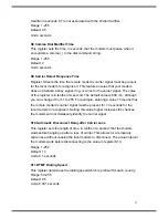
Page 27: ...though you can change it from 1 to 255 For example entering a value 13 means that the remote modem s carrier signal must be present for 1 3 seconds for the local modem to recognize it Setting this value higher increases the chances the modem will not mistakenly identify the carrier signal S10 Automatic Disconnect Delay after Carrier Loss This register sets the length of time in tenths of a second ...

Page 28: ...l Responses V1 default 4 5 Mapping to AT P 6 0 Use touch tone dialing method T default 1 Use pulse dialing method P 7 0 Answer incoming calls A 1 Originate calls D default S21 Bit mapped Register Bit mapped register S21 lets you control certain data communication control signals Bit Function 0 1 x Undefined 2 Mapping to AT R 3 4 0 Modem ignores the DTR signal D0 1 Modem enters command mode after O...

Page 29: ...art modem compatibility X0 4 Include CONNECT XXX responses X1 5 Same as 4 plus dial tone detection X2 6 Same as 4 plus BUSY response and blind dialing X3 7 Same as 6 plus dial tone detection X4 default 7 0 Undefined S23 Bit mapped Register Bit Function 0 1 2 3 0 0 300bps DTE data rate 1 1200bps DTE data rate 2 2400bps DTE data rate 3 4800bps DTE data rate 4 9600bps DTE data rate 5 14400bps DTE dat...

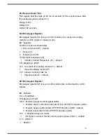
Page 30: ...eration only and applies only when you are using the R0 command This register determines how long the modem waits to turn on the Clear To Send signal after a Request To Send OFF to ON transition in 10 ms increment The default value is 1 Range 0 255 Default 1 Units 0 01 seconds S29 Bit Value Function 0 4 Mapping to AT I 5 7 Mapping to AT U S30 Inactivity Timer S30 specifies the length of time in mi...

Page 31: ...ster tells the status of the Local Phone It is read only 0 local phone on hook 1 local phone off hook S97 Bit Value Function 0 2 Mapping to AT Nn 7 Mapping to AT Cn S98 Bit Value Function 0 1 Mapping to AT H 2 Mapping to AT G 3 Mapping to AT T 4 6 Mapping to AT K S99 Energy detection threshold This register can use in Call Progress Mode CPM mode for dial tone detection threshold The default value ...

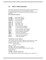
Page 32: ...lation FTH Check transmit HDLC data modulation FRH Check receive HDLC data modulation FMI Check manufacturer identification FMM Check product identification FMR Check version revision information FLO Select Flow Control specified FPR Select Serial Port Rate FCLASS Service Class Indication This command causes the modem to display the current setting The modem can operate either as a class 0 data mo...

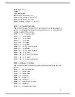
Page 33: ...3 V 21 Channel2 300 FTM 24 V 27ter 2400 FTM 48 V 27ter 4800 FTM 72 V 29 7200 FTM 96 V 29 9600 FTM 73 V 17 7200 FTM 74 V 17 short train 7200 FTM 97 V 17 9600 FTM 98 V 17 short train 9600 FTM 121 V 17 12000 FTM 122 V 17 short train 12000 FTM 145 V 17 14400 FTM 146 V 17 short train 14400 FRM m Receive FAX Data This command causes the modem to receive data at the modulation specified by m FRM 3 V 21 C...

Page 34: ...in 7200 FTH 97 V 17 9600 FTH 98 V 17 short train 9600 FTH 121 V 17 12000 FTH 122 V 17 short train 12000 FTH 145 V 17 14400 FTH 146 V 17 short train 14400 FRH m Receive HDLC Data This command causes the modem to receive data framed in the HDLC protocol at the modulation specified by m FRH 3 V 21 Channel2 300 FRH 24 V 27ter 2400 FRH 48 V 27ter 4800 FRH 72 V 29 7200 FRH 96 V 29 9600 FRH 73 V 17 7200 ...

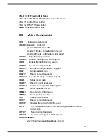
Page 35: ...g feature VDR Report current parameter VDR Queries the range that DCE support VGT Setup playback gain VGT Report current parameter VGT Queries the range that DCE support VGR Setup record gain VGR Report current parameter VGR Queries the range that DCE support FMI Report manufacturer ID FMM Report product information FMR Report product revision VIT Enable inactive timer VIT Report current parameter...

Page 36: ...back mode VRX Enter voice record mode VSM cml vsr cml 128 select linear 8bit PCM cml 132 select IMA ADPCM vsr xx Sample rate is always 8000 VSM Report current parameter VSM Queries the range that DCE support VPR rate DTE DCE rate will be equal 2400 rate but auto baud if rate 0 VPR Report current parameter VPR Queries the range that DCE support VLS pmode pmode 0 DCE on hook local phone connected to...

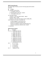
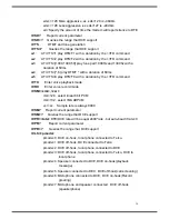
Page 37: ... 2 DTMF 2 tt3 3 DTMF 3 tt3 4 DTMF 4 tt3 5 DTMF 5 tt3 6 DTMF 6 tt3 7 DTMF 7 tt3 8 DTMF 8 tt3 9 DTMF 9 tt3 10 DTMF A tt3 11 DTMF B tt3 12 DTMF C tt3 13 DTMF D tt3 14 DTMF tt3 15 DTMF tt3 16 V32 9600 tt3 17 V32 14400 tt3 18 2100HZ ANSWER TONE tt3 19 1300HZ CALLING TONE tt3 20 1100HZ CALLING TONE tt3 21 tt3 22 Silence tt4 0 V21 Org tx mark tt4 1 V21 Org tx space tt4 2 V21 Ans tx mark ...

Page 38: ... ans tx guard tone if g1 or g2 tt4 11 V22bis ans tx guard tone if g1 or g2 tt5 0 V27ter 2400 tt5 1 V27ter 4800 tt5 2 V29 7200 tt5 3 V29 9600 tt5 4 V17 7200 short train tt5 5 V17 7200 long train tt5 6 V17 9600 short train tt5 7 V17 9600 long train tt5 8 V17 12000 short train tt5 9 V17 12000 long train tt5 10 V17 14400 short train tt5 11 V17 14400 long train ...

Reviews: