background image


35 | EN 

11. MEASUREMENTS TO BE DONE TO FIND THE FAULT COMPONENTS 
 

Components 

Power 


Lower resistance 

1200 W 

Turbo resistance 

1800 W 

Top resistance  / static 

1100 W 

Gril resistance 

2200 W 

Gril + top resistance (1100+1100) 

2200 W 

Turbo motor 

22-26 W 

Lamp 

15-25 W 


Current and power drawn by components on the product measured with the instrument 
called a multimeter. 


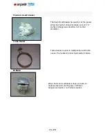
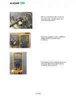
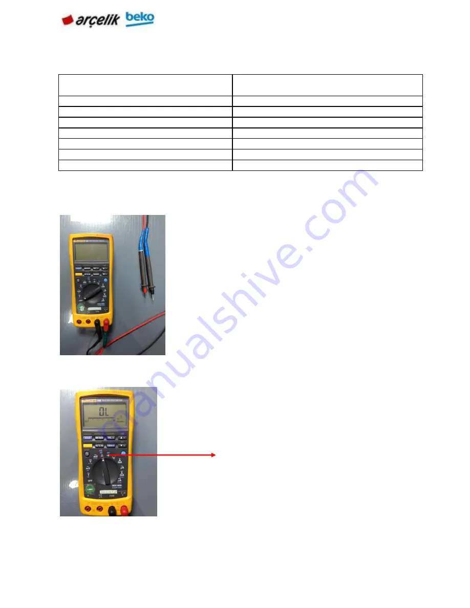
For the measurement of resistance Turbo example; 


Power of the components on the product 
is measured with an instrument that 
called multimeter. 

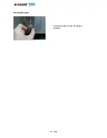
To measure resistance with multimeter, 
brought into position to measure the 
resistance of the resistor Turbo. 
 

Summary of Contents for BARBAROS

Page 1: ...1 EN BARBAROS BUILT IN BI OVEN SERVICE MANUAL ...

Page 2: ...CTS LABELS USED 22 7 1 PERIPHERALACCESSORIES 22 7 2 2 Barcode Label 23 7 3 3 Energy Label 24 8 GENERAL PRINCIPLE OF OPERATION 26 8 1 The Normal Operatıng Mode 27 9 LIST OF COMPONENTS COMPONENT WORKING PRINCIPLE 28 9 1 TECHNICAL SPECIFICATIONS OF THE COMPONENTS 28 9 2 COMPONENT CODE OF CONDUCT 28 10 FAULT FLOW FAULT FINDING DIAGRAMS 30 10 1 RESİSTANCE FAULTS 30 10 1 2 Resistance does not work the f...

Page 3: ...TION PLATE 54 AIR CONDITIONING THERMOSTAT REPLACEMENT 55 REMOVING THE REAR WALL 56 REMOVING THE SIDE DECOR 59 REPLACEMENT THE BOTTOM PLATE 59 CHANİNG THE SWİTCH 61 CATALYTIC REMOVAL OF THE INNER SIDE WALL 63 CHANGING THE GRID RESISTANCE 64 CHANGING THE OVEN HEATING 66 REPLACING TURBO RESISTANCE 68 REPLACEMENT OF OVEN SEAL 70 REPLACING TURBO ENGINE 71 CHANGING TERMINAL 73 REPLACEMENT THE TELESCOBIC...

Page 4: ...children without supervision Installation and repair procedures must always be performed by Authorized Service Agents The manufacturer shall not be held responsible for damages arising from procedures carried out by unauthorized persons which may also void the warranty Before installation read the instructions carefully Do not operate the product if it is defective or has any visible damage Contro...

Page 5: ... with the product Presure may cause the explosion Do not clean while the product is working Do not change in anything on the porduct or any repair instead of some problems in the user guide If there is no door or window for airing blower must be built Use a glove that is heat resistant during put remove the meal to the hot oven Do not use the product if front glass is broken or removed or any defo...

Page 6: ...5 kW Fuse min 16 A Cable type section H05VV FG 3 x 1 5 mm2 Cable length max 2 m External dimensions height width depth 595 mm 594 mm 567 mm Installation dimensions height width depth 590 or 600 mm 560 mm min 550 mm Main oven Multifunction oven Inner lamp 15 25 W Grill power consumption 2 2 kW ...

Page 7: ... carrying period To carry or move the product do not use door or handle of the product Door handle or hinges can be harmed Product should be carried by two person for safety of the product and ergonomics When the product is being carried or the product is being put to the ground do not put it keenly do not drag it and do not skid it from stairs ...

Page 8: ...in the mounting process please do not harm package product and the product package when extracting Take lathes on the product s front and behind sides like shown in below Extract package with a knife without harming top and bottom carton Take the top carton ...

Page 9: ...ing of them Preserve from damp Fragile Carry with barrow in this way Do not carry the product like in the picture Carry the product in this way by squeezing with clamp Do not step on the product Take stripers which are left and right side of the products ...

Page 10: ... kitchens bench so it is placeable Appropriate safety interval should be between kitchen wall and the furniture For appropriate interval please look at the picture values are mm type Used sides synthetic laminates and glues should be durable to the head min 100 C Product should be stayed with the same height with kitchen furnitures If there is a drawer bottom of the oven a shelf should be used bet...

Page 11: ...utlet line protected by a fuse of suitable capacity as stated in the Technical specifications table Have the grounding installation made by a qualified electrician while using the product with or without a transformer Our company shall not be liable for any damages that will arise due to using the product without a grounding installation in accordance with the local regulations Connection must com...

Page 12: ...duct Taking care not to break the jam and the power cord oven slide the cabinet slots align and fix it Right and left in the oven as shown in the figure screw holes for mounting the furnace furnishings Oven secure by means of screws as shown ...

Page 13: ...13 EN ...

Page 14: ...duct Plug in the power cord and turn on the insurance of the device 6 1 First Use 1 Function button 2 Temperature button 3 Temperature light Temperature and the selected operating mode 1 Function button 2 Temperature button ...

Page 15: ...he set temperature and maintains this temperature During heating temperature lamp illuminates Turning off the electric oven Turn the thermostat knob to the desired temperature Set the function switch to the desired operating mode ...

Page 16: ...ting Bottom Heat Function button and the temperature knob off upper position Top and bottom heating is on Foods are heated simultaneously from above and below For Example cakes are suitable for cakes and pies in casserole or baking mold Make cooking with a single tray Only the lower heating is on Pizza and the bottom is suitable for desired browning of food ...

Page 17: ...r heating rear wall open fan Hot air anywhere in the furnace evenly distributed fan and quickly Make cooking with a single tray You can do a lot of cooking tray Top heating bottom heating and warm air heating works Each side of the product to be cooked is cooked uniformly and quickly You can yapın çok baking tray with baking tray only Grilled effect is not as strong as in the normal grid ...

Page 18: ...is distributed evenly and quickly Very baking tray and can in most cases there is no need for preheating Food is used to keep the ready to long term service temperature Do not use for cooking food High temperature furnace used for self cleaning Read the descriptions for these functions in the maintenance and cleaning ...

Page 19: ...19 EN Using the clock Bakery Starting the cooking process Meal place in oven Set the cooking time by turning the knob clockwise to time Select the operating mode and temperature ...

Page 20: ...ssary up to pre heat for about 5 minutes When the cooking time is finished the rotary knob clockwise automatically reverse time Put the grid icon you want the function button Then set the grill temperature you want ...

Page 21: ...21 EN Closing the grid Function button to the off upper position ...

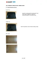
Page 22: ...S LABELS USED 7 1 PeripheralAccessories Oven Tray Cake Tray Wire Grid Used for pastries frozen foods and big roasts Used for roasting and for placing the food to be baked roasted or cooked in casserole dishes to the desired rack ...

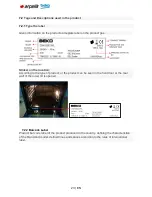
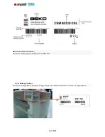
Page 23: ...ker on the location According to the type of product or the product can be seen in the front door or the rear wall of the lower lid is opened 7 2 2 Barcode Label Product bar code label of the product produced in the country defining the characteristics of the brand and model defined lines and spaces according to the rules of international label ...

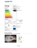
Page 24: ...24 EN Barcode label location Product packaging is pasted on cardboard 7 3 3 Energy Label Product energy label product energy class the label shows the volume of the product ...

Page 25: ...25 EN Energy Label lacatıon Energy label products are in a group of periodicals ...

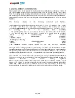
Page 26: ...t the endofthecooking time memories 1100 2200WHealth grill resistance 1800Whealthturbo resistance Healthupperovenheating 1100W Lower ovenheating1200W health 22Wness Fan Motor The rotisserie function feature works on the grill function Optional Although Fır any wrong operation is protected by a bi metal type thermal breaker Pyro ovens Bi metal type in an external furnace is on the left rear upper s...

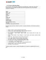
Page 27: ...heater works Statıc Fan Lower heater Upper heater and fan motor work Fan Cookıng Turbo heater and fan motor work 3D Cookıng Lower Heater Upper heater turbo heater and fan motor run sencronize Pizza Turbo Heater Lower Heater Lower heater turbo heater and fan motor work Grill Fan Upper Heater Grid and Fan motor work Grill Upper heater Grid and chicken rostıng work Small Grill Grid and Grid and chick...

Page 28: ...motor 22 26 W Lamp 15 25 W 9 2 Component Code of Conduct Grid Resistance Oven Heatıng Clemens Turbo Motor Turbo engine Turbo motor is used in multifunction and turbo motor It works alone in defrost mode When turbo motor works with resistance heat spreads homogenously Grid resistance is controlled by the control button under the commutator Oven heating is controlled by the control button under the ...

Page 29: ...e heat of chasis increase so much It works in dangerous situation not normal condition Turbo heater is used in multifunction and turbo ovens It is located in inner back wall of chasis When thermal circuit breaker does not work bi metal works and cuts the power It Works dangerous situation not normal situation ...

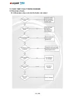
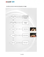
Page 30: ...30 EN 10 FAULT FLOW FAULT FINDING DIAGRAMS 10 1 Resistance Faults 10 1 2 Resistance does not work the food is not cooked ...

Page 31: ...31 EN 10 2 Lamp Fault 10 2 1 Furnace is working but the oven does not illuminate ...

Page 32: ...32 EN 10 2 2 Oven does not work oven lamp does not light ...

Page 33: ...33 EN 10 3 Termostat Fault 10 3 1 Furnace runs continuosly the thermostat is not tripped ...

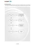
Page 34: ...34 EN 10 4 Therminal Fault 10 4 1There is no power from the terminal does not diffuse into the electric furnace ...

Page 35: ...1100 1100 2200 W Turbo motor 22 26 W Lamp 15 25 W Current and power drawn by components on the product measured with the instrument called a multimeter For the measurement of resistance Turbo example Power of the components on the product is measured with an instrument that called multimeter To measure resistance with multimeter brought into position to measure the resistance of the resistor Turbo...

Page 36: ... terminals of the coil with probes of a measuring instrument When the resistance works multimeter display shows the value of the resistance If the display of the multimeter does not show any value this means that you resistance does not work ...

Page 37: ...37 EN 12 COMPONENT ASSEMBLY DISASSEMBLY BE USED IN EQUIPMENT Screwdrivers needlenose Nippers ...

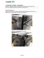
Page 38: ...ts disassembly operations are related below For component installations apply this operations in reverse order Removing the panel Before removing the board the top of the wall must be dismantled With the help of screwdriver remove the screws of the top wall connection ...

Page 39: ...39 EN Panels are connected with two screws to the front profile Panels were treated with 2 of each notch on the side pillars Remove the board from lifting upward notch ...

Page 40: ...40 EN You can change the idle board with a new one Changing the front cover Open the front cover ...

Page 41: ...41 EN Open the clips by pressing downwards as seen in the picture on the right and left front door hinge slot Turn the front door half open position Pull the door upwards and remove ...

Page 42: ...ver attaching the hinge slots in the cover will not close unless otherwise indicated Replacing the front door hinge Remove the front cover screws with a screwdriver After remove the screws on the hinges pull the empty slot and change with a new hinge ...

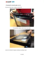
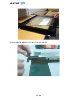
Page 43: ...43 EN Changing the removable glass cover 3 Remove the top decor located on the lid first Pull yourself to remove the front door inner glass Get in the middle of the glass remaining in pulling yourself ...

Page 44: ...44 EN After removing the screws pull as seen in the picture below ...

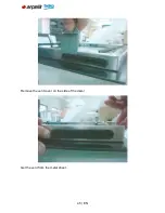
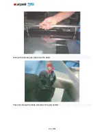
Page 45: ...45 EN Remove the vent cover on the side of the decor Get the vent from the metal sheet ...

Page 46: ...46 EN Changing The Handle To do this first remove the front cover Remove the screws of the handle with allen wrench as shown in the figure by 2 ...

Page 47: ...47 EN Pull out the handle grip pins down the drain This can change the blade remains in the grip handle ...

Page 48: ...48 EN Changing the upper wall Screw off the screws of the top wall Then lift the top wall up ...

Page 49: ...e the control panel Unplug the electrical connection plugs ot the comutator to be replaced Unbend the pins ot control panel Demount the pin ot comutator plasic placed in to hole on the control panel Turn the comutator plastic in clockwise direction to the plastic trom demount ...

Page 50: ...thermostat plastic pin trom the control panel Turn commutator plastic clockwise direction to remove the group trom the panel Replacement of the thermostat bulb Thermostat bulb is placed on the right top ot the rear wall ot the cavity To reach thermostat bulb upper and rear cover sheets should be demounted unscrew the screw ot bulb support sheet ...

Page 51: ...51 EN Pull the sheet away trom the cavity Pull the bulb away trom the support sheet Replace the bulb with new one and do operations ot demounting in reverse order to assemble the new bulb ...

Page 52: ...52 EN View ot the bulbin oven cavity can be seen in the picture ...

Page 53: ... thermostat has 2 screws Screw off these with a screwdriver Then remove and replace the thermostat with a new one Changing the engine cooling At the top of the chassis cooling ventilation keep the engine clockwise to remove and replace the engine ...

Page 54: ...54 EN Changing the ventilation plate Remove the top wall Screw off 2 screws that attached the ventilation to chassis ...

Page 55: ...ull the ventilation plate opposite of the red line Air conditioning thermostat replacement Remove the top of the wall before replacing the thermostat ventilation Ventilation thermostat is mounted with 2 screws ...

Page 56: ...56 EN By removing the air conditioning thermostat replace the screws Removing the rear wall ...

Page 57: ...57 EN Remove the 8 screws shown in the picture above ...

Page 58: ...58 EN Rear wall opens rıgh ward Lift the rear wall up by the area marked red ...

Page 59: ...he Side decor Remove the side walls Then screw off 3 screws that marked red in the picture below Replace tabs by removing profiles Replacement the bottom plate Bottom and sides of the oven has 10 screws Screw off these ...

Page 60: ...60 EN Remove the bottom of the base plate to ground as shown in the parts of the picture ...

Page 61: ...61 EN Chaning the switch Firstly you must detach the top wall to remove the swıtch So screw off side wall s screws Take on the swıtch that detached the side wall ...

Page 62: ...62 EN Remove the upper left side of the switch is down the drain and replace it in the oven Switch picture ...

Page 63: ...63 EN Catalytic removal of the inner side wall Firstly remove the wire shelves that are in front of the catalytic side walls Then screw off wire rack screws ...

Page 64: ...64 EN Replace the old catalytic side walls to new ones Changing the grid resistance Firstly remove the back wall and top wall then Remove the power cord of the resistance ...

Page 65: ...65 EN Screw off 2 screws Open the front cover Grid resistance has 2 screws that connects to the wall Screw off them ...

Page 66: ...from the plate Then insert new resistance s terminales by following electrical schematic and close the back wall Changing the oven heating For this operation remove the rear wall of the oven Then Remove electrical cords of the lower resistance ...

Page 67: ...67 EN Screw off the 2 screws Pull it yourself to remove resistance ...

Page 68: ...68 EN Pull it yourself to remove resistance Replacing Turbo resistance For this operation remove the top and back wall Then Remove the cables of Turbo resistance ...

Page 69: ...69 EN The fan cover plate has two screws Screw off them Then remove fan cover plate Turbo resistor has two screws that connect it to chasis Screw off them and replace turbo resistance with new one ...

Page 70: ...70 EN Replacement of oven seal Firstly open the oven door Chassis has notches to mount the seal Remove the seal from the specified places Then change with the new ...

Page 71: ...71 EN Replacing turbo engine For this operation Remove top wall rear wall and fan cover plate Disconnect the cables of the turbo engine ...

Page 72: ...72 EN Remove the turbo fan Turbo engine has 3 screws screw off them then replace the turbo engine then connect the electric terminals according to scheme of the new turbo engine ...

Page 73: ...ore you remove the rear wall then Open the terminal cover Terminal that connects to the rear wall and right in the box on the left marked in the picture Unscrew the screws with a screwdriver Remove the cables in the back wall of the terminal block ...

Page 74: ...74 EN Take the terminal box Replacement the telescobic rail Screw off the screw that connects wire rack with side wall Then replace the wire rack with the new one ...

Page 75: ...75 EN Replacing the oven lamp Remove the lamp s glass Replace the old lamp with new one ...

Page 76: ...76 EN Square oven lamp replacement Square lamp locates on the right side of chasis Detach the lamp by screwdriver ...

Page 77: ... Catalyzer is connected to the top wall with 3 nuts Screw off them to remove the catalyzer Replace the old catalyzer with new one Replacement the pyro door lock Firstly remove the top wall Metal sheet of pyro door lock is mounted at the top right side of chasis ...

Page 78: ...78 EN Screw off that connects to the chassis with a screwdriver Push the part that is on the side wall of pyro door door lock opposite of the red line like the picture above ...

Page 79: ... it with a new door lock idle Replacement the metal sheet of pyro ventilation Firstly remove the top wall Remove the plastic that is on the left side of metal sheet of air ventilation Screw off the 2 screws of the plastic ...

Page 80: ...80 EN Screw off the 2 screws that connect air ventilation with back panel of the oven ...

Page 81: ...81 EN Pull the metal sheet of air ventilation opposite of the red line that is shown the picture above Replacement the engine of pyro cooling Firstly remove the top wall ...

Page 82: ...off the 3 screws that connect cooling engine with the metal sheet of air ventilation Replace the engine with a new one Then check the wiring Replacement the engine thermostat of cooling Firstly remove the top wall ...

Page 83: ...83 EN Screw off 2 screws that connect thermostat with the metal sheet of air ventilation Then replace the thermostat with the new one ...

Page 84: ...Envelope IV 84 EN ...
Reviews: