2 | EN
1.CONTENTS……………………………………………………………………………………………………………………………….2
2.COVER……………………………………………………………………………………………………………………………………..3
3. SAFETY WARNING .................................................................................................................... 4
3.1
G
ENERAL
S
AFETY
............................................................................................................................... 4
3.2.
S
AFETY FOR
C
ONFİGURATİONS
............................................................................................................. 4
3.3
I
NFORMATİONS FOR
C
ONSUMER
........................................................................................................... 5
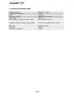
4. TECHNICAL SPECIFICATIONS ..................................................................................................... 6
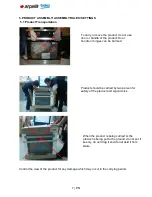
5. PRODUCT ASSEMBLY/ ASSEMBLY RULES/ SETTINGS ................................................................. 7
5.1
P
RODUCT
T
RANSPORTATION
................................................................................................................ 7
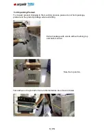
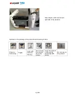
5.2
U
NPACKING
P
RODUCT
........................................................................................................................ 8
5.3
C
ONTROLLING THE SETUP PLACE AND ENERGY SOURCES
. .......................................................................... 10
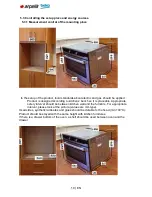
5.3.1 Measurement control of the mounting place ...................................................................... 10
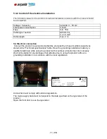
5.3.2 Control of the electrical installation ..................................................................................... 11
5.4
E
LECTRİCAL CONNECTİON
................................................................................................................... 11
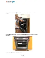
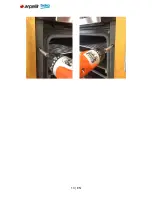
4.3.2 Instead of mounting the product ......................................................................................... 12
6. USE OF THE PRODUCT ............................................................................................................ 14
6.1
F
İRST
U
SE
....................................................................................................................................... 14
6.2
W
ORK
F
UNCTIONS
........................................................................................................................... 16
6.1.6 Work Functions ..................................................................................................................... 16
U
SING THE CLOCK
B
AKERY
....................................................................................................................... 19
7.BY PRODUCTS/PRODUCTS LABELS USED .................................................................................. 22
7.1
P
ERIPHERAL
A
CCESSORIES
.................................................................................................................. 22
7.2.2 Barcode Label ....................................................................................................................... 23
7.3.3 Energy Label; ........................................................................................................................ 24
8. GENERAL PRINCIPLE OF OPERATION ....................................................................................... 26
8.1 The Normal Operatıng Mode .................................................................................................. 27
9.
LIST OF COMPONENTS / COMPONENT WORKING PRINCIPLE................................................... 28
9.1
T
ECHNICAL SPECIFICATIONS OF THE COMPONENTS
; ................................................................................. 28
9.2
C
OMPONENT
C
ODE OF
C
ONDUCT
........................................................................................................ 28
10.
FAULT FLOW / FAULT FINDING DIAGRAMS ........................................................................... 30
10.1.R
ESİSTANCE
F
AULTS
....................................................................................................................... 30
10.1.2 Resistance does not work;the food is not cooked .............................................................. 30
10.2
L
AMP
F
AULT
................................................................................................................................. 31
10.2.1 Furnace is working but the oven does not illuminate ........................................................ 31
10.2.2 Oven does not work,oven lamp does not light, .................................................................. 32
10.3
T
ERMOSTAT
F
AULT
......................................................................................................................... 33
10.3.1 Furnace runs continuosly,the thermostat is not tripped. ................................................... 33
10.4
T
HERMİNAL
F
AULT
......................................................................................................................... 34
10.4.1There is no power from the terminal does not diffuse into the electric furnace ................ 34
11. MEASUREMENTS TO BE DONE TO FIND THE FAULT COMPONENTS ........................................ 35
Summary of Contents for BARBAROS
Page 1: ...1 EN BARBAROS BUILT IN BI OVEN SERVICE MANUAL ...
Page 13: ...13 EN ...
Page 21: ...21 EN Closing the grid Function button to the off upper position ...
Page 25: ...25 EN Energy Label lacatıon Energy label products are in a group of periodicals ...
Page 31: ...31 EN 10 2 Lamp Fault 10 2 1 Furnace is working but the oven does not illuminate ...
Page 32: ...32 EN 10 2 2 Oven does not work oven lamp does not light ...
Page 33: ...33 EN 10 3 Termostat Fault 10 3 1 Furnace runs continuosly the thermostat is not tripped ...
Page 37: ...37 EN 12 COMPONENT ASSEMBLY DISASSEMBLY BE USED IN EQUIPMENT Screwdrivers needlenose Nippers ...
Page 44: ...44 EN After removing the screws pull as seen in the picture below ...
Page 45: ...45 EN Remove the vent cover on the side of the decor Get the vent from the metal sheet ...
Page 48: ...48 EN Changing the upper wall Screw off the screws of the top wall Then lift the top wall up ...
Page 52: ...52 EN View ot the bulbin oven cavity can be seen in the picture ...
Page 56: ...56 EN By removing the air conditioning thermostat replace the screws Removing the rear wall ...
Page 57: ...57 EN Remove the 8 screws shown in the picture above ...
Page 58: ...58 EN Rear wall opens rıgh ward Lift the rear wall up by the area marked red ...
Page 60: ...60 EN Remove the bottom of the base plate to ground as shown in the parts of the picture ...
Page 67: ...67 EN Screw off the 2 screws Pull it yourself to remove resistance ...
Page 75: ...75 EN Replacing the oven lamp Remove the lamp s glass Replace the old lamp with new one ...
Page 80: ...80 EN Screw off the 2 screws that connect air ventilation with back panel of the oven ...
Page 84: ...Envelope IV 84 EN ...


