background image

AVR350

E-7

E

n

g

li

s

h

Audio connections

Wherever possible, connect both the analogue and digital outputs of digital sources. This enables 
use of a digital input for the main zone and the corresponding analogue input for recording onto 
an analogue tape deck or VCR, and for the Zone 2 output if used.

Take care to place the audio cables as far from any power supply cabling as is practically possible 
to reduce hum and other noise problems.

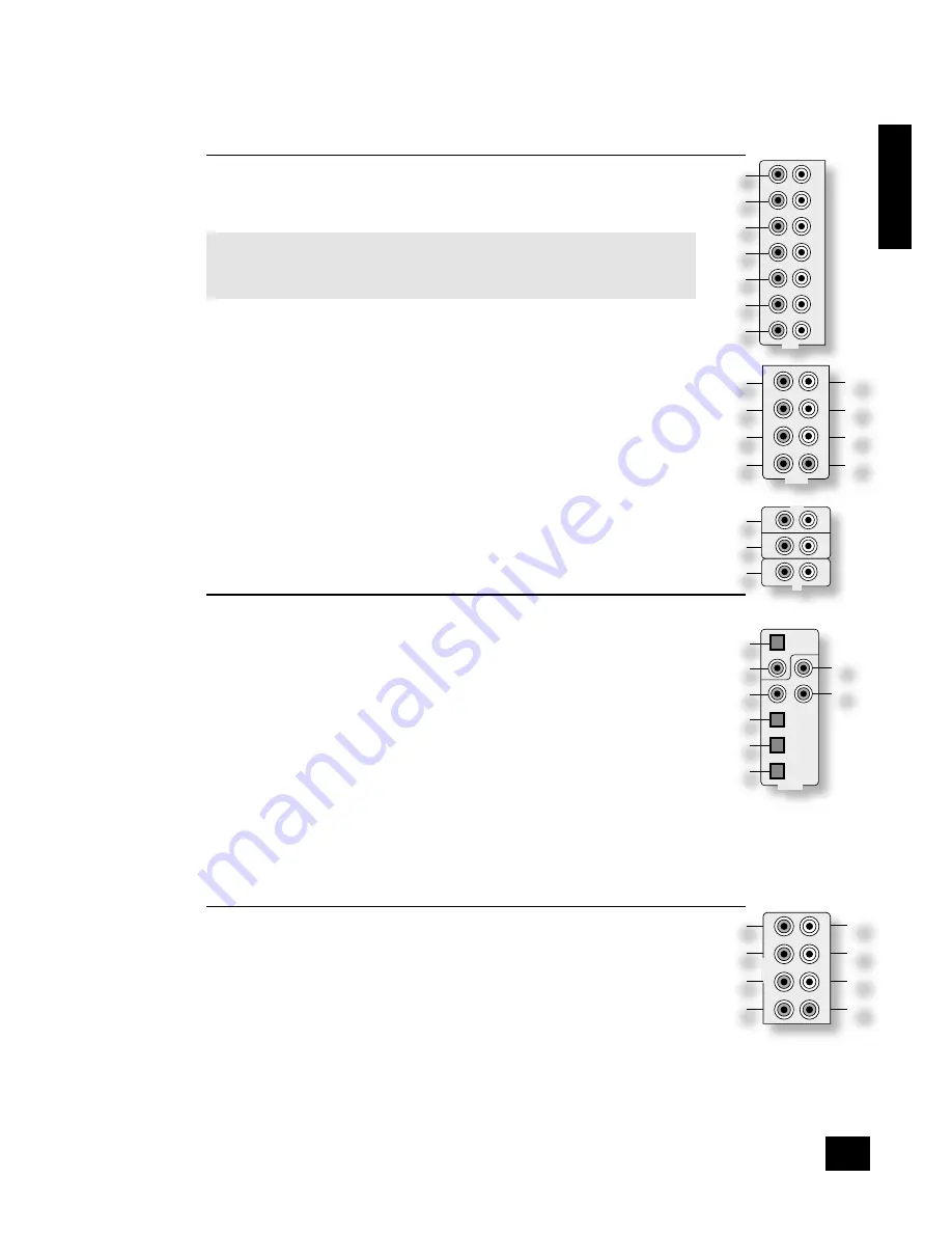
Analogue audio connections

STereo InPuTS

2


VCR

4


PVR

5


AV

6

 SAT

7


DVD

br


TAPE IN

bs

 CD

.  

Connect the left and right outputs of your source equipment to the left and right inputs.

Connection of record decks:

The AVR350 is not fitted with a phono pre-amplifier. If you wish to connect a record deck 
to the AVR350, then you will need an external pre-amplifier. Please contact your dealer for 

further information and recommendations on the best option for your system.

MulTI-CHannel DVD-a/SaCD InPuTS

8


RIGHT

9


LEFT

bk


RIGHT SURROUND

bl


LEFT SURROUND

,  

bo


CENTRE

bp


SUB

.  

Connect the audio outputs of your DVD-Audio or SACD player to these input sockets.

bm


RS BACK

, and 

bn


LS BACK

.  

These are available for formats requiring eight channels. Currently no formats are available 
requiring these connections, which are provided for future compatibility.
The multi-channel input is intended for use with sources that decode the surround channels 
internally, such as DVD-A or SACD players.
The AVR350 switches these analogue inputs directly to the analogue outputs via its own volume 
control circuit. This direct path maintains the best possible sound quality for DVD-A and SACD 
sources; it has the side-effect that there is no bass-management for DVD-A or SACD players. In 
this case, the bass-management functionality of the player itself should be used.

STereo ouTPuTS

1


VCR OUT, 

3


PVR OUT, 

bq


TAPE OUT

.  

Connect the left and right audio outputs sockets to the left and right input sockets of your cassette 
deck, VCR or PVR (usually labelled ‘RECORD IN’). The VCR/PVR connections may also be used for a 
second or third cassette deck.

Digital audio connections

InPuTS

cl


CD

cm


DVD

cn


AV

co


SAT

cp


PVR

cq


TAPE

.

Connect the digital ouputs of your available source equipment to these inputs.
If required, each of these six digital inputs can be allocated to a different audio input from that 
indicated by the input label, through the ‘Digital Settings’ page of the Set-up menu. This means that, 
for example, if you wish to use an optical connection for your DVD player, the optical connection for 
the SAT, PVR, or TAPE can be used and the audio from that digital input assigned to the 

DVD

 button.

ouTPuTS

bt


ck


DIGITAL OUT

.

Two digital output connections are available: optical and coaxial. The two connections carry the same 
information at all times and both may be used simultaneously. Connect the digital outputs to your 
digital recording devices such as a CD-R, digital VCR or MiniDisc player.

When a digital source is selected,

 the digital output will send an exact copy of the incoming digital 

signal. For example, for a 5.1 digital source, the digital output will also be in 5.1 format.

When an analogue source is selected,

 the digital output will be muted. These outputs are also muted 

if a source is selected where the only connection for that source is HDMI. The digital audio from the 
HDMI link (if any) is not routed to these outputs.

Analogue pre-amplifier outputs

The pre-amplifier outputs are used to send signals to external power amplifiers. This may be 
either for ‘bi-amping’ speakers or for use with a more powerful external amplifier (such as the 
Arcam P7 seven-channel amplifier). Note that if you wish to bi-amplify speakers, you must use an 
amplifier with the same gain as the AVR350 (31dB), otherwise the bass and the treble will become 

unbalanced. Please contact your dealer if you require more information on bi-amping your speakers.
All these analogue outputs are buffered and are at line level.

co


RIGHT

cp


LEFT

dk


CENTRE

. Connect these to the equivalent front channel inputs of your power 

amplifier.

dl


SUB

. Subwoofer output. Connect this to the input of your active subwoofer, if you have one.

cq


L SURR

. Surround left output. Connect this output to the surround left power amplifier input.

cr


R SURR

. Surround right output. Connect this output to the surround right power amplifier input.

cs


LS BACK

ct


RS BACK

 Surround back left and right outputs (only used in 7.1 channel systems). 

Connect these outputs to the inputs of your LS back and RS back amplifiers.

1

AUDIO

OUT

IN

VCR

OUT

IN

PVR

AV

SAT

DVD

R

L

2

3

4

5

6

7

��
��

��

��
��

��

DVD-A IN

FR

RS

RSB

CEN

FL

LS

LSB

SUB

DIGITAL IN

DIGITAL

OUT

CD

AV

DVD

SAT

PVR

TAPE

��
��

��

��

��
��

��
��

OUTPUTS

FR

RS

RSB

CEN

FL

LS

LSB

SUB

��
��

��

��

��
��

��

��

TAPE

CD

R

L

IN

IN

OUT

��

��

��

Summary of Contents for AVR350

Page 1: ...AVR350 HANDBOOK Arcam AVR350 surround sound receiver English...

Page 2: ...stand that is recommended for use with audio equipment If the equipment is on a portable rack it should be moved with great care to avoid overturning the combination 8 Cleaning Unplug the unit from th...

Page 3: ...o channel source modes E 27 Multi channel source modes E 27 DSP Effects Modes E 28 Speaker positioning E 28 Bi wiring and bi amping loudspeakers E 29 Before you start important information E 29 Bi wir...

Page 4: ...in a listening room is an important process which requires care at every stage For this reason the installation information is very comprehensive and should be followed carefully Using this handbook T...

Page 5: ...conversion for Zone 2 For these reasons we recommend that source devices that have a digital connection are also connected to the analogue inputs High quality YUV RGB and S video sources should also...

Page 6: ...or VCR but all inputs have the same circuitry This means that there is no reason why you should not connect a different device from that labelled to any of the inputs For example if you had two DVD pl...

Page 7: ...ital inputs can be allocated to a different audio input from that indicated by the input label through the Digital Settings page of the Set up menu This means that for example if you wish to use an op...

Page 8: ...urces to these inputs en HIGH QUALITY VIDEO OUT Connect these sockets to the component video inputs of your display device Important notes about HQ video inputs and outputs In the Video Settings set u...

Page 9: ...n of the instruments and the sense of direction of the stereo being impaired There are two options for connecting the speaker cable to the amplifier Using bare wire ended leads 1 Strip back the insula...

Page 10: ...not use those marked TV which should be connected to the FM in socket fr of the AVR350 If you wish to use the supplied FM ribbon cable mount this as high up as possible on a wall with the T elements p...

Page 11: ...GGER 2 These trigger outputs have different functions depending on how the Video Status has been set in the General Settings menu See page 10 for full details Connecting to a power supply fo Power inl...

Page 12: ...Pressing the menu button for just a short time will take you to Main Menu Screen 1 If this happens the Main Menu can be closed by pressing menu for a second time 2 When the menu heading is highlighted...

Page 13: ...e the video triggers or a SCART connection then it does not matter which value this item has This item has four settings Composite S video RGB and Scrn Ctrl Composite This mode is used to indicate to...

Page 14: ...frequency at which bass redirection begins Frequencies below this level are redirected from small speakers to the Fronts or to the subwoofer frequencies above this level are not redirected The value f...

Page 15: ...ti channel analogue outputs of an Arcam DVD A player then this item should be set to 10dB 4 Speaker Delay Settings The relative positioning of speakers within a room may mean that sound from some spea...

Page 16: ...peaker that is not selected in the previous Speaker Sizes menu Note that inserting headphones into the front panel of the AVR350 will cause all test tones to be muted including the headphone output No...

Page 17: ...Inputs Composite and S video inputs for DVD Sat AV VCR and PVR have their audio and video assigned to track each other by default The five Video Input lines for Tape CD FM AM and DVD A allow assignme...

Page 18: ...ogue inputs in Volts rms so that each one achieves the optimum dynamic range and sounds similar in loudness to the others Available level settings are Low 0 5V Medium 1V Reference 2V High 4V The refer...

Page 19: ...the AVR350 to be put into and taken out of stand by remotely If you do not wish to put Zone 2 into stand by at the same time as the main zone press and hold the stand by button on the remote control f...

Page 20: ...on on the remote control Volume control To adjust the volume level of the loudspeakers pre amp outputs and headphones use the volume control knob The volume level is shown on the display Note that dif...

Page 21: ...rent source from CD will cause the recording to change to this new source VCR PVR Operation The AVR350 has VCR and PVR record loops for audio and video Composite and S video only These carry the audio...

Page 22: ...s in Speaker Eq is still 6dB not 12dB To select the speaker to be adjusted press the Treble Bass button repeatedly until the desired speaker is shown on the front panel display Then use the volume con...

Page 23: ...ion you wish to store Press the STORE button or DYN on the remote control the station frequency is shown on the display followed by a preset number Select the preset number you wish to assign to the s...

Page 24: ...ct buttons on the front panel or the remote Note that changing the audio input also changes the video input to the same setting Video Input This shows the current video input source selected The curre...

Page 25: ...ing immersive result We recommend Dimension is set to 3 for normal use Centre Width With Pro Logic decoding dominant centre signals come only from the centre speaker If no centre speaker is present th...

Page 26: ...ember this for all bitstream sources e g DTS ES Matrix Dolby Digital 3 0 etc and use the maximum number of speakers the signal is encoded for As a result when a 2 0 or 2 1 bitstream is played the Surr...

Page 27: ...ight stereo sources can sound muffled and compressed DTS NEO 6 DTS Neo 6 provides up to six full band channels of decoding from stereo material The AVR350 will derive separate channels corresponding t...

Page 28: ...round left surround right left surround back right surround back and an active subwoofer see diagram All speakers with the exception of the subwoofer should be arranged around your normal viewing list...

Page 29: ...speaker terminals the speakers will still be single wired 2 Connect the cables as shown in the diagram ensuring correct polarity at all times Bi amping your system Notes In order to bi amplify your sp...

Page 30: ...mplifiers are in use it is recommended to route pairs of channels through the same amplifier e g the front left and right channels should be amplified by the same amplifier Connect the HF terminal of...

Page 31: ...n the HQ Video setting is set to RGB you will have a pink red OSD To correct this you must set the HQ Video line on the General Settings menu to Component No On Screen Display OSD overlaid on video Th...

Page 32: ...2 Settings in the Set up Menu When Zone 2 is put into stand by the main zone is also turned off Check that the Zone 2 Stand by line of Zone 2 Settings in the Set up Menu is set to Local Only Unstable...

Page 33: ...mand Command code Command Command code Stand by 124 Mode 32 On 123 Mono mode 106 Zone 1 stand by 125 Stereo mode 107 Power toggle 12 Dolby PLII Movie 108 Display DIS 59 Dolby PLII Music 109 Menu Menu...

Page 34: ...ressed for 1 second 5 Command Command code Preset 6 preset 14 if pressed for 1 second 6 Preset 7 preset 15 if pressed for 1 second 7 Preset 8 preset 16 if pressed for 1 second 8 Preset 9 9 Preset 10 1...

Page 35: ...and 7 Sleeve Coaxial cable 6 and 7 18 Ground RGB switching control Stereo Mini Jack 3 5mm Sleeve Screened cable 19 Video output composite RCA Phono 6 Centre Coaxial cable 6 Comp out 20 Video input co...

Page 36: ...and 96kHz Digital output level impedance 0 5V 75 Trigger outputs Output D C voltage level excl RGB status 12V 1V Allowable load 30mA max min 400 Remote inputs and output Signal modulated 36kHz carrie...

Page 37: ...ransportation costs at any time Claims under guarantee This equipment should be packed in the original packing and returned to the dealer from whom it was purchased or failing this directly to the Arc...

Page 38: ...e the parameters for the reponse ETR End transmission 0xd The AVR350 responds to each command from the RC within three seconds The RC may send further commands before a previous command response has b...

Page 39: ...me AVR350 Si le menu Set up est ferm en raison de l ouverture d un autre menu toute modification apport e au menu Set up est perdue d Aufrufen eines der Men s des AVR350 Falls das Set up Men aufgrund...

Page 40: ...f S quence commande r ponse pour fermer le menu Main d Befehls R ckmeldesequenz zum Schlie en des Hauptmen s n Opdracht en responsreeks om het hoofdmenu te sluiten Command 0x50 0x43 0x5f 0x2d 0x31 0x3...

Page 41: ...Beispiel Voorbeeld g Example command response sequence to decrment the volume by 1dB in Zone 2 where the resulting volume is 56dB f S quence commande r ponse pour baisser le volume de la zone 2 de 1...

Page 42: ...iste waarde verkrijgen dan moet u 0x30 van de gerapporteerde waarde aftrekken Formule feitelijk volume gerapporteerd volume 0x30 De opdracht kan hierdoor waarden vereisen retourneren die niet in ASCII...

Page 43: ...the decode mode to Pro Logic IIx Movie Mode f S quence commande r ponse pour remplacer le mode de d codage par le mode Pro Logic IIx Movie d Befehls R ckmeldesequenz zur nderung des Dekodiermodus in...

Page 44: ...mix 0x30 DD 5 1 0x31 DD EX 0x32 DD 5 1 PLIIx Movie 0x33 DD 5 1 PLIIx Music 0x34 DTS Mono down mix 0x35 DTS Stereo down mix 0x36 DTS 5 1 0x37 DTS ES 6 1 Matrix 0x38 DTS ES 6 1 Discrete 0x39 DTS 96 24...

Page 45: ...s lection re ue 0x30 d Aktuelle Frequenz in einer Voreinstellung abspeichern Der bertragene ausgegebene Wert der Voreinstellung ist um 0x30 versetzt Formel aktuelle Voreinstellung empfangene Voreinst...

Page 46: ...ported freq MHz FM freq kHz reported freq kHz 0x30 x 10 For these reasons this command may return values that cannot be translated into ASCII characters f Augmentation diminution de la fr quence du tu...

Page 47: ...0x30 de la valeur rapport e Formule pr s lection r elle pr s lection rapport e 0x30 d Ausw hlen einen spezifischen Tuner voreinstellen Der ausgegebene Wert f r die neue Voreinstellung ist um 0x30 vers...

Page 48: ...Pembroke Avenue Waterbeach CAMBRIDGE CB5 9QR England www arcam co uk Issue 1 SH174E...

Reviews: