


SET-UP AND SAFE OPERATING PROCEDURES
5-11
89210000
0
20
40
60
80
100
D.C.
VOLTS
0
2000
500
1000
1500
D.C.
AMPERAGE
0 0
MODE
CC
CP
JOG
FEED
RETR
AUTO
MAN
START
STOP
2
1
0
3
4
TRAVEL
TRAVEL
DELAY
ARC
LEVEL
CONTROL
POWER
Automatic Control
1
2
3
4
5
6
9
8
7
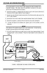
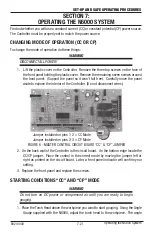
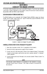
FIGURE 2 - Front of Automatic Controller
1. CONTROL-POWER SWITCH:
Turns on the power when pushed in. The electrode retracts
and the cooling fan in the Contactor starts.
2. MODE-INDICATOR LIGHT:
Indicates the operating mode (either “CC” constant current or
“CP” constant potential) of the Controller. The setting should match the welding power
source. If it doesn’t, see Section VII, page 7.
3. JOG SWITCH FOR/REV:
Moves the electrode in the torch head prior to gouging.
4. TRAVEL-DELAY CONTROL:
Delays the travel system until the arc current flows (for the
set period of time). This delay permits the electrode to reach the right depth before moving
forward. It works only when the travel system is plugged into the “TRAVEL” receptacle on
the Controller and the travel switch is in the “AUTO” position.
5. TRAVEL SWITCH AUTO/MAN:
Allows the travel system to start automatically or manually.
The travel system must be plugged into the “TRAVEL” receptacle on the Controller.
NOTE
This receptacle may be used to run any device that has the same line-voltage
requirements and that requires “On-Off” or “Start-Stop” control. However, any
such device must be rated with a maximum current draw of 5 amperes.
6. START/STOP BUTTON:
Starts or stops the gouging operation. The REMOTE PENDANT will
also start or stop gouging.
NOTE
For this system to operate the Pendant Assembly or Jumper Connector must be
attached to the Controller.
7. ARC LEVEL CONTROL: Sets arc voltage when the Controller is in the “CC” mode. When the
Controller is set in the “CP” mode, this dial sets the amperage.
The N6000 Automatic System