


WEKA_IOM_VLI_EN / 17.03.2020
16 / 31
12.
Cleaning visual level indicator
12.1
Cleaning the outside
Polycarbonate indication rails may become statically charged – e.g. during cleaning. Sparks
created when discharging in a potentially explosive atmosphere may cause an explosion. Only
clean these parts with antistatic cleaning agents and tools.
Caution
Solvents and scouring agents may cause the indication rail window to become dull or cracked. Clean the
window with soapy water or a plastic cleaner.
12.2
Cleaning the float chamber and the float
Risk of burning! Working on hot visual level indicators may result in physical injuries and burns.
The surfaces of the standpipes and the process connections may become hot. Allow the tank to
cool to the ambient temperature before working on the visual level indicator. Wear suitable
protective equipment (gloves, face guard, possibly breathing apparatus). Keep a sufficient
distance away while the machine is in operation.
Visual level indicators run at excessive pressure carry pressure-related risks. Depressurise the
tank before working on the visual level indicator and observe the information of the local valid
pressure regulations, i.e. Pressure Equipment Directive 2014/68/EU.
When opening the visual level indicator, bear in mind that the fluids and gases it contains could
be hazardous to health. It is imperative that you comply with the safety data sheets for the
process liquids and gases used.
Falling parts (screws, floats, etc.) may create impact sparks and lead to an explosion in
potentially explosive atmospheres. Make sure that there isn’t a potentially explosive atmosphere
and that no parts are falling when working on the visual level indicator.
When using highly contaminated fluids or pipe systems, the float and the float chamber need to be cleaned
frequently.
In fluids with magnetic parts, they cluster on the float’s magnet. Remove them
frequently.
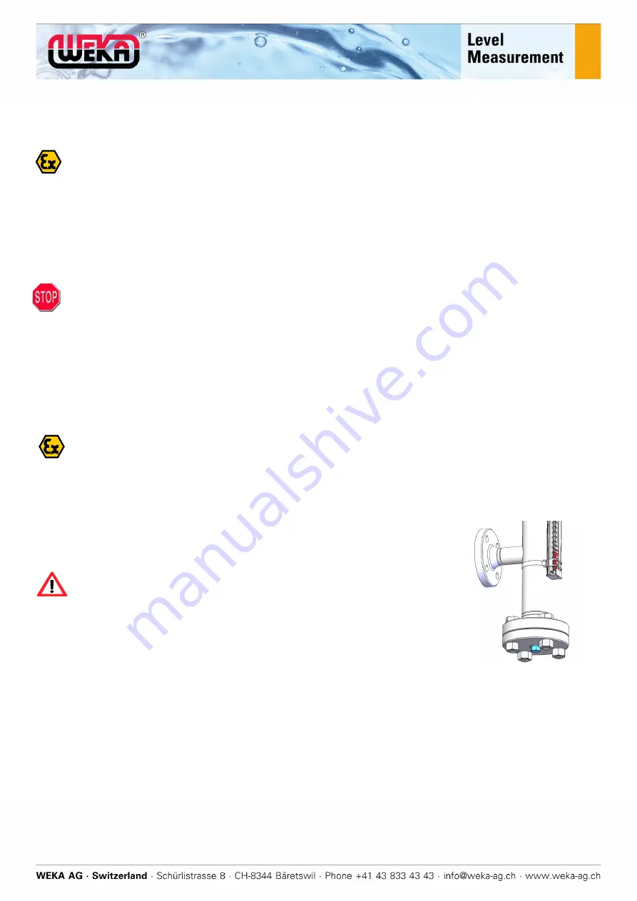
1. Empty the tank.
The float may fall out and get damaged when you remove the
connection flange.
Remove the float chamber via the lower service connection, see
Figure (Service plug/flange).
Remove the lower service plug/flange and the float.
2. Clean the float chamber and the float with a suitable cleaning agent.
Summary of Contents for 23013
Page 1: ...Installation and Operating Manual Visual Level Indicator VLI Date 17 03 2020 Version E 10 1...
Page 2: ...WEKA_IOM_VLI_EN 17 03 2020 1 31 Notes Order Date...
Page 23: ...WEKA_IOM_VLI_EN 17 03 2020 22 31 20 EU Declaration of Conformity for explosion proof devices...
Page 24: ...WEKA_IOM_VLI_EN 17 03 2020 23 31 21 ATEX Certificate Type Examination Certificate...
Page 25: ...WEKA_IOM_VLI_EN 17 03 2020 24 31...
Page 26: ...WEKA_IOM_VLI_EN 17 03 2020 25 31...
Page 27: ...WEKA_IOM_VLI_EN 17 03 2020 26 31 22 IECEx Certificate of Conformity CoC...
Page 28: ...WEKA_IOM_VLI_EN 17 03 2020 27 31...
Page 29: ...WEKA_IOM_VLI_EN 17 03 2020 28 31...


