


4 Mounting & Connecting the Electrical System
13
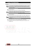
When wiring an ARB compressor switch,
Air Locker
pressure switch,
Air Locker
actuator
switch(es) and
Air Locker
solenoid(s) to an ARB Air Compressor, all connections can easily
be set up using only the supplied wiring loom (ARB #180409 shown in Figure 7.)
F
Consulting the wiring diagram (Fig.7.) for wire colors, and the switch terminal illustration
(Fig.8.), plug each of the female spade terminals onto their appropriate switch terminal.
IMPORTANT :
As a safety precaution, the ‘SWITCH 2’ position in the wiring loom will not
activate unless ‘SWITCH 1’ is already activated. Therefore, if both front and rear
Air Lockers are installed then the rear MUST be controlled by ‘SWITCH 1’, and
the front by ’SWITCH 2’. This is a safety feature that serves to reduce the risk of
accidental / unintended engagement of the front Air Locker.
If only one Air Locker is installed then it should be wired using the terminals for
‘SWITCH 1’, regardless of whether the Air Locker is mounted in the front or rear axle.
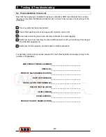
Figure 8.
NOTE : FRONT / REAR AIR LOCKER switches are supplied with each Air Locker
differential kit, not with this compressor kit.
F
Using a multimeter or an automotive test light, locate an accessory outlet or cigarette
lighter port in the vehicle.
NOTE : The desired outlet should supply positive 12 volts DC, be fused at a
minimum of 8 amps, and be live only when the vehicle ignition key is in
either the ‘ACC’ position or in the ‘ON’ position.
F
Using a soldering iron or automotive quality crimp connectors, splice the red wire with a
yellow stripe (RED-YEL) found on the separate short section of loom onto the positive (+)
wire of the accessory outlet pair.
NOTE : If shortening the RED-YEL wire, make sure not to remove the heat shrinked
inline diode that protects sensitive electronics from current leakage.
F
Insulate the junction area well with electrical tape.
F
Using a multimeter or an automotive test light, locate an active dash light supply wire.
NOTE : The desired wire should supply 12 volts DC (less if dimmed) and react to the
illumination level of the instrumentation / dash light dimmer.
F
Using the scotch lock connector (supplied) splice the blue wire with a white stripe (BLU-
WHT) found on the separate short section of loom onto the active illumination supply
wire.
COMMON BACK
OF SWITCHES
FRONT OF SWITCHES