8
6
CONNECTIONS
6.1
Hydraulic motor (OIL) connections
6.1.1
Safety guidelines
- Use tubes that are suitable to the motor flowrate and pressure (ref. Tab. 1).
- Fix the hydraulic tubes checking that after their use under pressure there are no blow-by or oil leakages from the circuit.
- Do not install the pump where it can be subject to severe impacts, or where there is too much heat or in any other point that
can cause the machine to malfunction.
-During the insertion in an existing system, follow all the safety guidelines indicated by the system manufacturer.
-Qualified staff must carry out any type of intervention that requires the modification of the original hydraulic connection
configuration.
ARAG is not liable for damages to equipment, persons, animals or property caused by wrong or unsuitable pump connections.
Furthermore, ARAG can not be held responsible for direct or indirect damages to equipment, machinery, persons or animals
caused by the use of pipes, cable clamps, ties, or any other connection or by the use of unsuitable and improper accessories.
Damages to the pump or to the circuits/objects connected to it, due to the above-mentioned causes, automatically voids the
warranty.
6.1.2
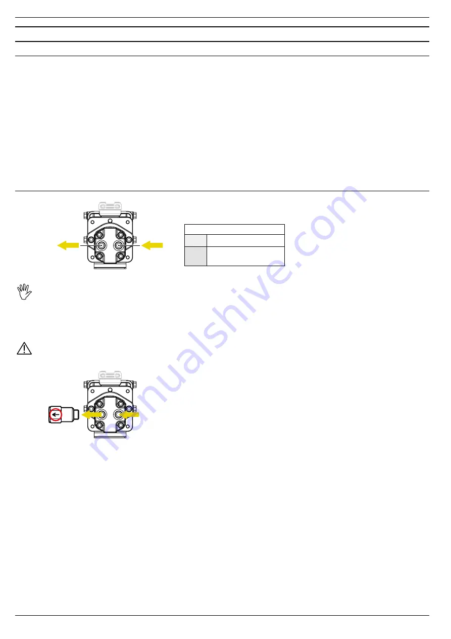
Hydraulic motor oil line connection
in
out
IMPORTANT:
TO AVOID THE BREAKAGE OF THE MOTOR, PAY ATTENTION NOT TO INVERT THE OIL TUBES CONNECTION.
For this purpose, it is recommended to install a check valve.
ARAG check valve (Code 970001 - Ref. ARAG Catalog), to be purchased separately, must be installed in the oil output branch
(out) PAYING ATTENTION TO THE REFERENCE OF THE FLOW DIRECTION, as indicated on the valve body (Fig. 7).
Use the gaskets provided and a tightening torque of 20 Nm.
ARAG is not liable for damages to the system, persons, animals or property caused by the use of a check valve different from the
one indicated. The warranty is to be considered automatically void in case of damages to the pump caused by failure to observe
the above-mentioned instructions.
- The maximum value of the back pressure on the outlet is 3 bar.
- The oil outlet line (drain) should be directed into the oil tank.
- The pipelines must have a nominal diameter not lower than the diameter of the fittings on the motor and they must be perfectly
sealed.
- To avoid loss of pressure, the pipelines should be as short as possible reducing to a minimum the number of hydraulic
resistances (elbows, bottle necks, quick-couplings).
- It is advisable to place a section of flexible tube in between the pipelines, this is to reduce the transmission of vibrations.
- All the return pipelines must end below the minimum oil level, this is to avoid the formation of foam.
- Before connecting the pipelines, remove all closing plugs, if any, and make sure they are perfectly clean.
oil
inlet
oil
outlet
Oil tubes diameter
in
1/2"
out
1/2" - max length 10 m
or
3/4" - no length limit
Fig. 6
Tab. 5
Fig. 7


