background image

11

6.5 

Starting and operating

   Fig. 13

6.6 

Topping up liquid

• 

Depressurize the tank as indicated in par. 6.1 - Discharging remaining pressure.

• 

Refill with liquid, observing the procedures described in the par. 6.4 - Preparing foaming 
solution.

• 

Use only ARAG foaming agents.

• 

IN CASE OF DAMAGES TO THE FOAM MARKER CAUSED BY NON AUTHORIZED 
FOAMING AGENTS, ALL WARRANTY CLAUSES WILL BECOME NULL AND VOID.

6.6.1  Foaming agents

CODE

CONTENT

PACKAGES

520050

5 lt / 1.32 US gal.

tank

520035

25 lt / 6.6 US gal.

tank

520033

200 Kg / 441 lb

barrel

• 

Operate the selector lever (

A

, Fig. 12) onto the control box and 

start the compressor.

• 

The indicator turns on and the circuit reaches the operating 
pressure after a few seconds causing the foam to come out 
from the selected foam maker.

• 

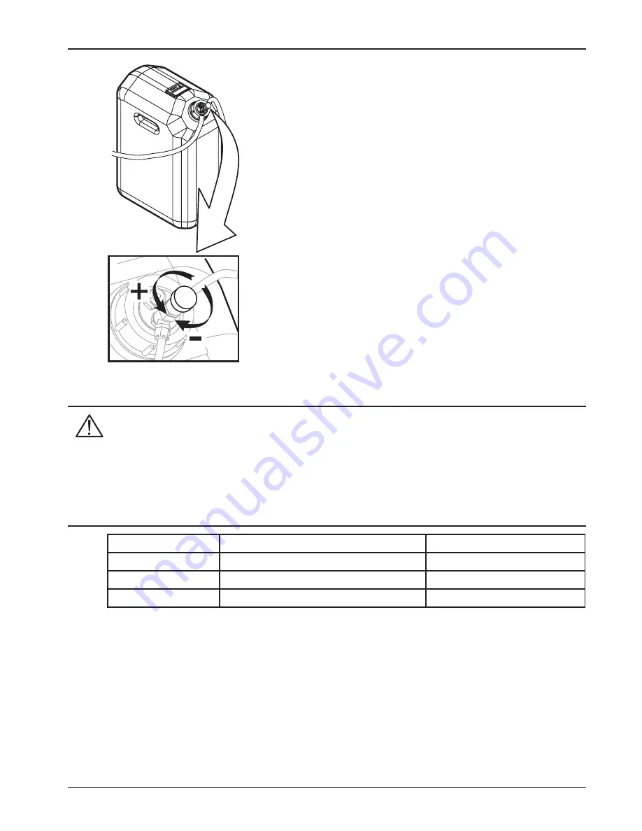
Adjust the intensity of the foam outlet, using the flow-rate 
regulator on the tank cap (Fig. 13).

• 

During use it is possible to alternate the right- or left-hand 
foam nozzle by moving the selector lever.

• 

To interrupt foam marker operation, set the switch to its central 
position (OFF).

Summary of Contents for 520005

Page 1: ...FOAM MARKER 520005 520005C 5200052 5200052C 02 INSTALLATION uSE AND MAINTENANCE...

Page 2: ...t of the equipment to which it refers and must accompany the equipment in case of sale or change of ownership Keep it for future reference ARAG reserves the right to modify the specifications and inst...

Page 3: ...9 5 9 Final testing 9 6 Use 10 6 1 Discharging remaining pressure 10 6 2 Control devices 10 6 3 Preliminary checks 10 6 4 Preparing foaming solution 10 6 5 Starting and operating 11 6 6 Topping up liq...

Page 4: ...methods and acceptance criteria 2 precautions Foaming agents in general are potentially toxic Only use the foam marker outdoor or in well ventilated environments wearing the required individual protec...

Page 5: ...he boom Fix the pipes of the pneumo hydraulic system to the framework with clamps in a position pro tected from possible impact with the ground or with the boom framework At the joints of the booms th...

Page 6: ...6 5 2 Overall dimensions mm inches 5 3 Assembly diagram 1 Control box 2 Tank and compressor unit 3 Foam makers Fig 4 Fig 5...

Page 7: ...1 Fix the compressor unit C to the tank holder basket B and then install the assembly onto the machine 2 Install compressor unit C and tank holder basket B separately Should this be the case the comp...

Page 8: ...he tubes to the compressor unit ensuring that each tube is connected to a connector of the same color Connect the foam marker which is the nearest to the compressor unit and repeat the above procedure...

Page 9: ...w the cap onto the tank fully 3 Move the selector A Fig 12 to the right and start the compressor unit 4 Ensure that fluid comes out from the right foam marker after some seconds 5 Check the correct se...

Page 10: ...the product see par 6 6 Add clean water to fill the tank using a pipe inserted down to the bottom of the tank so as to mix the product well and prevent foam from forming Screw on the cap and tighten i...

Page 11: ...DE CONTENT PACKAGES 520050 5 lt 1 32 US gal tank 520035 25 lt 6 6 US gal tank 520033 200 Kg 441 lb barrel Operate the selector lever A Fig 12 onto the control box and start the compressor The indicato...

Page 12: ...hown in Par 6 1 Slacken the band B and remove the diffusor A Only for horizontal foam markers Fig 14a completely slacken the bands and remove the diffuser in the arrow s direction Wash the diffuser A...

Page 13: ...ove the cap C Remove tank A and wash with clean water Wash the bottom filter D with clean water Fit the tank into the retaining basket Add a few litres of water into the tank put the cap back on Resto...

Page 14: ...0005 353 provided with the package Proceed as follows Fig 18 7 7 Fuse replacement Before replacing the fuse disconnect the control box from the battery Fig 19 Lift the fuse holder cap A onto the power...

Page 15: ...ug and on the outer pipes Clean the bottom filter of liquid Check for any constrictions along the pipes Foam formation is not good Sponge dirty or hardened Clean or replace the sponge in the generator...

Page 16: ...t draw at 12 Vdc 9 A Working temperature 0 C 40 C 32 F 104 F Tank capacity 27 l Working pressure at 12 Vdc 0 75 bar Max pressure valve setting 1 bar Water foam agent solution consumption 35 l h max To...

Page 17: ...17 520005 5200052 520005C 5200052C 520005 900 10 Spare parts...

Page 18: ...18 520005 060...

Page 19: ...19 520005 080...

Page 20: ...20 520005 260 520004 262...

Page 21: ...21 520005 390...

Page 22: ...tallation and regulation damage or malfunction caused by the lack of ordinary maintenance such as cleaning of fi lters nozzles etc anything that can be considered to be normal wear and tear 3 Repairin...

Page 23: ...004 108 CE e successive modificazioni Compatibilit Elettromagnetica 97 23 CE e successive modificazioni Attrezzature in pressione 98 37 CE e successive modificazioni Macchine Riferimenti alle Norme Ap...

Page 24: ...ITALY Via Palladio 5 A Tel 0522 622011 Fax 0522 628944 http www aragnet com info aragnet com Only use original ARAG accessories and spare parts to maintain safety conditions foreseen by the construct...

Reviews: