Model 2500A225C
Rev A
29
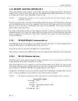
2.10 REMOTE CONTROL INTERFACES
This section describes remote operation of the amplifier using the provided General Purpose Interface Bus
(GPIB), RS-232 serial port, fiber-optic serial ports, Universal Serial Bus (USB), and Ethernet port. All ports
are always active; however, only one port may be used at a time.
*NOTE:
Communicating through two or more ports at one time will cause data collisions and lost
commands or queries.
The Keylock switch on the control panel of the amplifier enables the remote-control functionality and must be
set to the REMOTE position before any commands will be accepted. All remote queries will work with the
Keylock switch in any position. When the Keylock switch is set to REMOTE, all front panel controls are
disabled unless otherwise specified.
The status of the amplifier should be checked remotely just prior to issuing a command as well as after a
command has been issued to ensure the command has been properly executed. When checking the status after
issuing a command, it is good practice to add a delay of 100ms or more to allow the control system time to
process the command.
2.10.1
GPIB (IEEE-488) Communications
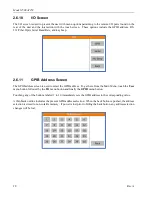
For GPIB operation, the device address is set using the front panel touch screen. For more information about
setting the GPIB address, see the GPIB Address Screen, section 2.6.9.
Ensure that each device connected to the GPIB is set to a unique address.
When sending commands via the GPIB interface, terminate commands with an EOI and a Line Feed character.
2.10.2
RS-232 Communications
The RS-232 port is a serial communications bus. When a valid query is received, it is processed, and the result
is immediately transmitted back over the RS-232 interface.
Once the first character of a new command or query has been transmitted to the amplifier, any pause between
a subsequent character (or the termination character) greater than 5 seconds will result in the internal buffer
being cleared and a TIMEOUT_ERROR<LF> message being sent out on this port.
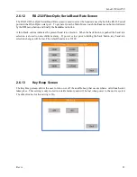
The baud rate for the RS-232 port is user-selectable from the RS-232/Fiber-Optic Serial Baud Rate selection
screen. For more information, see User Interface section of this document, section 2.6.
*NOTE:
The baud rate settings are shared by both the RS-232 port and the Fiber-Optic serial port.
General RS-232 settings
Word Length: 8 bits
Stop Bits: 1
Baud Rate: User-selectable (default is 19200)
Parity: None
HW Handshake: None
Summary of Contents for 0053007
Page 2: ......
Page 4: ......
Page 6: ......
Page 18: ...Model 2500A225C iv ...
Page 28: ......
Page 70: ...Model 2500A225C 46 Rev A ...
Page 80: ...Model 2500A225C 56 Rev A Figure 4 7 SMA Module Input Figure 4 8 Final Module RF Output ...
Page 82: ...Model 2500A225C 58 Rev A ...
Page 84: ...Model 2500A225C 60 Rev A ...
Page 86: ......


