Model 2500A225C
Rev A
23
2.6.16
ALC Lockout feature
The ALC lockout feature allows users to lock all ALC settings and remain in the ALC Internal Mode regardless
of a power cycle. Under normal operating conditions these settings can be changed at any time and reset with
a power cycle.
Since the ALC can be used to limit the amplifier output level, the ALC lockout feature can be used as a safety
system to prevent users from having access to the amplifier’s full potential. This can be useful during debugging
of control software where preventing accidental high-powered RF output is crucial.
The ALC system uses three values to automatically level the RF output. These values are Threshold, Detector
Gain, and Response Time. When the ALC lockout is initiated, the current values for Threshold, Detector Gain,
and Response Time are stored to non-volatile memory.
On power up, when in the ALC locked state, the amplifier will automatically go to ALC Internal mode and use
the ALC values read from non-volatile memory. Also, while in the locked state, the ALC values and the
amplifier mode selection cannot be changed. The locked state is indicated by the disappearance of the Select
and Mode menu options on the touch display. In addition, while in the locked state, the Adjust knob is
automatically tied to the RF Gain adjustment which remains adjustable regardless of the ALC lockout state.
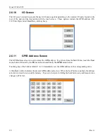
To access the ALC lockout feature, the user must navigate to the GPIB address screen (
User, I/O, GPIB
Address
) and enter the password 23, 15, 5, 3, 1 (See figure below). The current GPIB address setting will not
be lost during this process unless the Back button is pressed before the password is successfully entered. Once
the password is correctly entered, the ALC Lockout screen will appear. The present ALC values are indicated
on the ALC Lockout screen and menu options to lock or unlock the ALC system are presented. The user must
select Lock, Unlock or cycle power to cancel. After a selection is made, the user must cycle power to begin
using the amplifier in the selected state.
Remotely, the ALC Lockout state affects the Level Adjust and the Mode Select commands. In the locked state,
the Level Adjust command for ALC Threshold, Detector Gain, and Response Time are simply ignored. This
is also true of the Mode Selection. These commands can be issued to the amplifier while in the locked state,
but their associated values will not change regardless of the Keylock position. Queries of these settings using
the Machine State command and the State command are always permissible in either the locked or unlocked
state regardless of the Keylock position.
Summary of Contents for 0053007
Page 2: ......
Page 4: ......
Page 6: ......
Page 18: ...Model 2500A225C iv ...
Page 28: ......
Page 70: ...Model 2500A225C 46 Rev A ...
Page 80: ...Model 2500A225C 56 Rev A Figure 4 7 SMA Module Input Figure 4 8 Final Module RF Output ...
Page 82: ...Model 2500A225C 58 Rev A ...
Page 84: ...Model 2500A225C 60 Rev A ...
Page 86: ......


