


16
EN
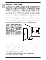
CONNECTING THE HEAT PUMP TO THE POWER SUPPLY NETWORK
Before connecting to the power supply
network, install a power supply cord in
the heat pump, with a min. diameter of
1.5 mm
2
(H05VV-F 3G 1.5 mm
2
). To do
this, remove the protective cover from the
heat pump. The cover is attached using
two screws (Fig. 9). Connecting the heat
pump to the power supply network must
take place in accordance with the
standards for electric appliances. To
comply with the national installation
regulations, an all poles disconnect
switch must be installed between the heat
pump and the power supply network.
Fig. 9: Protective cover
Legend:
QUART
PROG.
BUZZ1
K4
K9
K6
K5
K1
K11
K3
K10
K7
FAS5
FAS4
FAS1
FAS3 FAS2
8
7
4
T1
10
00
W
6
10
00
W
T2
T3
1
2
3
4
1
2
3
4
5
2
1
1
2
1
2
1
2
L
N
5
10
9
C
R
S
1
2
3
4
4
3
2
1
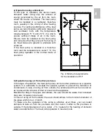
Fig. 10: Electrical circuit diagram
T1 - Bar with sensors
T2 - Evaporator – temp. sensor
T3 - Air temperature sensor
1 - 4-way valve
2 - Compressor
4 - Fan
5 - Electric heating element
(2 x 1000 W)
6 - Thermal cut-out
7 - Magnesium anode
8 - LCD touch screen
9 - Boiler - ground
10 - Housing - ground
Summary of Contents for PAW-DHWM 80-120 ZNT
Page 1: ...PAW DHWM 80 120 ZNT ...
Page 24: ...24 EN ...
Page 48: ...48 DE reparieren sondern nehmen Sie mit dem nächsten autorisierten Kundendienst Kontakt auf ...
Page 120: ...120 DA ...
Page 144: ...144 NO ...
Page 168: ...168 SV ...
Page 192: ...192 HR BIH ...
Page 216: ...216 CS ...
Page 240: ...240 HU ...
Page 264: ...264 PL ...
Page 267: ...267 ...
Page 268: ...09 2014 479748 ...


