background image


10 


Version 1.0 
Update: August 2018 
 

AQUALABO 
90 Rue du professeur P. Milliez 
94506 Champigny-sur-Marne, FRANCE 
Tel.: +33(0)1 55 09 10 10  

4.1.2 Accessories for PVC pipe-mounting. 

 
Every  system  of  assembly  is  delivered  with  an  adapter  (and  the  appropriate  joints)  and  one  T  of 
assembly (90 ° for CTZN sensor) to stick on a 90 mm diameter pipe. Its special design type ensures 
the correct inflow to the sensor, thus preventing incorrect measurements. 
 
Please note the following when planning your piping set-up: 
• The fitting must be easily accessible to allow the sensor or the fitting itself to be maintained 
and cleaned regularly 
• We recommend bypass measurements. It must be possible to remove the sensor through 
the use of shut-off valves 
• When working with systems involving pressure and/or temperature, ensure that the fitting 
and sensor meet all relevant requirements 
• The system designer must check that the materials in the fitting and sensor are suitable for 
the measurement (chemical compatibility, for instance) 


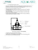
Mounting system for CTZN sensor (

PF-ACC-M-00001

 
1 Unscrew the union nut (2) from the PVC flow fitting (3). 
2 Guide the sensor cable through the union nut on the fitting. 
3 Insert the sensor (1) into the fitting as far as the position shown in the middle image above. 
4 Screw the union nut onto the fitting as far as the stop.


 CTZN sensor 
 
Union nut 


Adapter 


90 mm pipe diameter 

Summary of Contents for Ponsel CTZN

Page 1: ...1 Version 1 0 Update August 2018 AQUALABO 90 Rue du professeur P Milliez 94506 Champigny sur Marne FRANCE Tel 33 0 1 55 09 10 10 CTZN NUMERICAL SENSOR User manual ...

Page 2: ...3 1 Product overview 6 3 2 Applications 6 3 3 Construction and dimensions 6 3 4 Communication 7 3 4 1 Modbus RTU registers 7 3 4 2 SDI12 frame 8 4 INSTALLATION 8 4 1 Sensor installation option 8 4 1 1 Accessories for immersion installation 8 4 1 2 Accessories for PVC pipe mounting 10 4 1 3 Accessories for stainless steel pipe mounting 11 4 3 Electrical connections 12 5 STARTUP AND MAINTENANCE 13 5...

Page 3: ...iliar with and comply with the instructions in this manual Make sure the power supply complies with the specifications before connecting the device A clearly labeled power switch must be installed near the device Check all connections before turning the power on Do not attempt to use damaged equipment it may represent a hazard and should be labeled as faulty Repairs must only be carried out by the...

Page 4: ...ge temperature 10 C à 60 C Maximum refreshing time Maximum 1 seconde Sensor Dimensions Diameter max 62 4 mm Lenght 196 mm Weight 700 g Wetted Material Body EPDM PVC Stainless steel Cable polyurethane jacket Steam gland Polyamide Maximum pressure 5 bars Connection 9 armoured connectors polyurethane jacket bare wires or waterproof Fisher connector Protection IP68 Sensor cable Standard 3 7 and 15 m o...

Page 5: ...liance with the European standards Standard tests EN 61326 1 edition 2013 Emission EMC EN 55022 Class B Immunity EN 61000 4 3 A EN 61000 4 2 B EN 61000 4 6 A EN 61000 4 4 B Shone disturbances EN 55011B Identification of the measurement process composed of 1 one probe 2 Ponsel s cable EN 61000 4 5 Not concerned for sensors with a cable lower or equal to 30 M Commercial name DIGISENS range Manufactu...

Page 6: ...e required High measuring accuracy even for low concentrations Rapid response times The sensor features excellent interference immunity thanks to the integrated preamplifier and digital signal processing The measured value for conductivity is automatically compensated with the temperature and transferred without interference to the connected display unit and controller via a digital interface The ...

Page 7: ...ameter temperature of the Sensor and to calibrate the parameter temperature Furthermore there are certain numbers of functions such as Select the averaging value Read the Sensor description Return to default coefficients Modify the Sensor address Information on measures conducted Out Of Specification measures measures in progress etc Date and name of the operator who performed the calibration etc ...

Page 8: ...e cable at the risk of damaging the sensor AQUALABO proposes a range or pole long version in order to install the sensor in open basins It can be positioned a considerable distance from the basin edge with the bracket suspended for example Please note the following when planning your set up The fitting must be easily accessible to allow the sensor or the fitting itself to be maintained and cleaned...

Page 9: ...le and specially studied to adapt themselves to the different configurations of assembly Elbowed pole with elbowed shutter PF ACC C 00109 90 ELBOW LONG POLE FOR CTZN SENSOR 2955 mm ELBOWED SHUTTER Straight long pole with elbowed shutter PF ACC C 00115 STRAIGHT LONG POLE FOR CTZN SENSOR 2745 mm ELBOWED SHUTTER Elbowed shutter Vertical axis Connection vertical pole horizontal axis Connection horizon...

Page 10: ...ined and cleaned regularly We recommend bypass measurements It must be possible to remove the sensor through the use of shut off valves When working with systems involving pressure and or temperature ensure that the fitting and sensor meet all relevant requirements The system designer must check that the materials in the fitting and sensor are suitable for the measurement chemical compatibility fo...

Page 11: ...e acceptable maximum pressure for the sensors is 5 bars The system of assembly can be delivered with or without stainless steel clamp The adapter is compatible with a 90 mm diameter external clamp Mounting system for CTZN sensor PF ACC C 00350 1 After welding the clamp 3 on the stainless steel pipe remove the clamp from the system and remove the PVC adapter 1 2 Guide the sensor cable through the u...

Page 12: ...3 2 V Consumption Standby 25 µA Average RS485 1 measure seconde 6 3 mA Average SDI12 1 measure seconde 9 2 mA Current pulse 500 mA Protection against the inversions of polarity Wiring diagram Cable length up to 15m 1 Red Power supply V 2 Blue SDI 12 3 Black Power supply V 4 Green B RS 485 5 White A RS 485 6 Green yellow Cable shield with Power supply V Cable lenght 15 to 100 meters Red Purple Yell...

Page 13: ...lization before measure processing Started 5 2 Calibration The calibration of the conductivity sensor is a 2 step process Step 1 offset Expose the sensor to the air to perform the first stage of the Calibration process The value for this first calibration standard is set to 0 0 μS cm Step 2 gain the sensor is placed in a buffer solution of known conductivity 12 88 mS cm Let stabilize during 5 minu...

Reviews: