background image

8

GB

Set Up Instructions

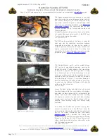
8. Prior to installing the head unit, turn it over, remove 

the impeller cover extension pipe so you can see the 
impeller.  Make  certain  that  the  power  cord  is  not  wet 

and plug it into the receptacle. Turn it on and ensure 

the impeller is spinning and that the UV-C works. You 

should be able to hear the impeller spinning and see 

the blue light from the UV-C. 

DO NOT LOOK AT THE 

BLUE LIGHT FROM THE UV-C FOR MORE THAN A 
SECOND.  DO  NOT  OPERATE  THE  UV  WITH  OUT 
WATER  FOR  MORE  THAN  A  FEW  SECONDS

.  The 

switch for the UV-C is located at the top of the head unit 

on the side behind the frosted plastic cap. When the UV 

light is on the green LED located next to the switch will 

illuminate, if the UV lamp stops working for whatever 

reason  the  LED  will  turn  off.    If  the  impeller  does  not 

turn or the UV-C does not light up see Cleaning Your 

Filter for instructions on how to assess the impeller and 

UV Lamp. Fig 7

10.  NOTE:  The  O-ring  needs  to  be  put  into  position 

before the unit is set up. Lubricate it with an aquarium 
safe lubricant.

This  lubrication  allows  the  head  unit  to  go  on  easily, 

ensures a good water tight seal and makes removing 

the head unit easier when maintenance is required. IT 

IS VERY IMPORTANT THAT ANY TIME THE FILTER 

IS  DISASSEMBLED  THE  O-RING  IS  LUBRICATED 

USING AN AQUARIUM SAFE LUBRICANT. Fig 8

Place the Impeller cover extension pipe pipe back into 

position before placing the head back on the canister.

12. Close the 2 handles. Do not force the unit together! 

If  it  feels  tight  do  not  apply  any  excess  pressure  to 

close it simply, remove the head unit and filter baskets 

and try again. Fig 9

13.  Latch  and  secure  the  clips. The  filter  unit  is  now 

ready to be installed.  Fig 10

11.  Place  the  head  unit  back  on  top  of  the  canister 
body;  ensure  the  power  cord  is  not  jammed  between 

filter head and the canister body. Press down gently to 

the point where the head will not go any further.

Fig 7

Fig 2

Fig 7

Impeller

UV-C 
Switch 

Fig 8

O-ring

Summary of Contents for Nautilus 2700UVC

Page 1: ...Inspiring Excellence in Fish Keeping Nautilus 2700UVC www aquaone com au Instruction version 27 02 2011 ...

Page 2: ...6 7 8 9 11 11 12 13 14 14 15 16 Seiten 18 19 19 20 21 22 23 25 25 26 27 28 28 29 30 Précautions importantes Avant la première utilisation Préparation Découvrez votre filtre Installation recommandée pour les matériaux de filtration Instructions de configuration Instructions d installation Démarrage de votre filtre Nettoyage de votre filtre Changer votre lampe UV Dépannage Spécifications Belangrijke...

Page 3: ... wet do not unplug the appliance Disconnect the fuse or circuit breaker that supplies the power to the appliance then unplug and examine for presence of water in the socket 5 Always unplug the appliance from the electrical outlet when not in use before putting on or taking off parts before any type of maintenance or cleaning 6 Never yank the cable to pull it from the socket Pull the plug carefully...

Page 4: ...ound and the product has been assembled This product is shipped to you in a factory sealed carton Should the product malfunction in any way or if the unit is damaged and requires replacement contact the retailer where the product was purchased for inspection Replacement Parts Filter Media Use Aqua One Genuine Spare Parts Only See your local Aqua One Dealer and look for the number listed below for ...

Page 5: ...mmended Filter Media Set Up Nautilus 2700UVC CeramiSub Wool Sponge Black 35ppi Sponge Black 35ppi Sponge Blue 15ppi BioNood Sponge Blue 15ppi CeramiSub Media Basket 1 Media Basket 2 Media Basket 3 Media Basket 4 ...

Page 6: ...r media baskets are sitting flat on top of each other You will notice there is one basket which is different to the others This must be the last tray to be inserted Fig 6 1 Open the filter unit To do this release the 2 clips located on either side of the filter Fig 1 3 Take the canister body to the sink Ensure the area is clean and free from detergents 4 Remove the filter media baskets from the ca...

Page 7: ...w to assess the impeller and UV Lamp Fig 7 10 NOTE The O ring needs to be put into position before the unit is set up Lubricate it with an aquarium safe lubricant This lubrication allows the head unit to go on easily ensures a good water tight seal and makes removing the head unit easier when maintenance is required IT IS VERY IMPORTANT THAT ANY TIME THE FILTER IS DISASSEMBLED THE O RING IS LUBRIC...

Page 8: ... inlet and the outlet You will find the required components in the remaining plastic bags 1 Remove all remaining components from the plastic bags 2 Locate your quick release tap connections Ensure the collars on the hose tails are all the way in the locking lever is in the up right position and that the O rings are lubricated Fig 1 3 Insert the quick release tap connector into the top of your filt...

Page 9: ... e 7 Surface Skimmer f 8 Intake Pipe g 9 Pipe connector h 10 Suction Cup i 11 Strainer j Fig 8 Lock nut Hosetail Hose a b c d f g g j e h i i 1 U Pipe a 5 Spray Bar e 2 Lock Nut b 6 End Cap f 3 Hose Tail c 7 Suction Cup g 4 Elbow d d g a b c e e e f g g Fig 6 Fig 7 11 Refer to Figure 7 to assist you in assembling the intake You will find that the U Pipe a Locking Nut b and Hose Tail c come as one ...

Page 10: ...the Spray Bar 2 Place your mouth over the end of the outlet U Pipe and create siphon effect by sucking on the tube 3 Once the siphon begins lower the outlet tube into a bucket 4 Now wait until the siphon continues to fill the canister and eventually overfill into the bucket via the outlet U Pipe 5 The filter is primed when the intake pipe and filter is completely filled with water 6 Nowplaceyourth...

Page 11: ...This build up will reduce the flow rate of your filter considerably so clean when ever it is possible 23 Return the canister filter to your cabinet or stand and reattach quick release tap connector 24 Refer to the section in this instruction manual Starting You Filter for details on restarting the unit Cleaning your filter 1 Turn the canister filter off at the socket and unplug 2 Place a towel or ...

Page 12: ...13 GB Cleaning your filter Threaded elbow Grommet Impeller Impeller chamber Head Impeller Cover Shaft O ring UV C Housing UV Lamp ...

Page 13: ...on restarting the unit Trouble Shooting THE FILTER UNIT IS LEAKING 1 Check all O rings are in place and that they are not damaged or soiled 2 Re apply Silicon based aquarium safe lubricant 3 The media baskets may not aligned properly 4 Ensure the quick release tap connector is inserted correctly and locked into position THE FILTER WILL NOT PRIME 1 Check tubing for kinks 2 Make sure the Quick relea...

Page 14: ...er the tap where the hose has been removed and blow into the hose 5 This will create pressure in the canister body and pop the head unit off If the filter is new and the head unit is on tight simply attach the tap unit and ensure the locking lever is down so the taps are open Ensure all clips are released Cap either the IN or OUT with your hand and blow into the other This will create pressure and...

Page 15: ... on its packaging indicates that the product must not be disposed of with normal household waste Instead it is your responsibility to dispose of your waste equipment by arranging to return it to a designated collection point for the recycling of waste electrical and electronic equipment By separating and recycling your waste equipment at the time of disposal you will help to conserve natural resou...

Page 16: ...chase 2 5 Where Aqua One determines goods are being used in a manner contrary to the instructions specifications or this Guarantee Aqua One reserves the right to terminate Extended Guarantee for such goods and will provide written notice to the purchaser 3 0 Exclusions and Limitations Where permitted by local law the following exclusions and limitations apply in regard to Guarantee 3 1 Goods claim...

Reviews: