


8 |
P a g e
PLEASE NOTE:
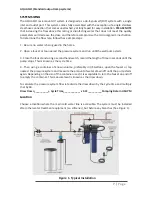
All AQUA FLO UV disinfection systems are intended for indoor use only as they
should not be exposed to the elements. The controller will require a ground fault circuit inter-
rupter (GFCI or GFI) outlet and should be mounted beside or above the reactor.
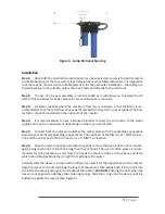
Orientation
This system has the ambidextrous capability of being able to have the main water inlet enter
from either the left hand side or right hand side of the unit. The units comes pre plumbed from
the factory for a left hand water inlet. To change to a right hand water inlet follow these simple
steps (See Figure 2):
Step 1:
Remove the blue filter sump housings (either one or two housings depending on the
model purchased) from the filter head and set aside.
Step 2:
Remove the filter head screws from the top mounting plate (4 screws for a single filter
model and 8 screws for a double filter model).
Step 3:
Carefully lower the filter head (or heads) from the rack assembly and rotate 180 de-
grees. Reassemble onto the rack assembly and take note of the arrows located on the top of the
filter heads indicating water flow (which now should be indicating a flow direction of right-to-
left).
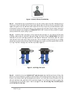
Step 4:
Remove the stainless steel UV reactor from the two plastic clamps located on the top
of the rack. Carefully remove the top straps securing the reactor with the aid of a standard (slot)
screwdriver). Rotate the reactor 180 degrees (with the inlet now facing to the left and the lamp
connections located towards the right) and place back into the cell clamps and re affix the two
top straps.
In either the left or right configurations, to facilitate lamp removal, ensure there is enough space
at the lamp connector end to safely remove the UV lamp and/or quartz sleeve (See Figure 3).
Figure 2. System Orientation (water inlet)


