


1 5 |
P a g e
Operation
AQUA FLO systems come with a feature laden controller that incorporates both the lamp driver
(ballast) and control features in one water-tight case. Two controllers are available for the AQUA
FLO systems (depending on your model).
Controller
These controllers feature a power factor corrected, constant
current lamp driver with a universal power input. A full co-
lour LCD screen provides the user with a detailed descrip-
tion of the system’s performance in addition to providing
any applicable fault messages and system diagnostics. The
controllers used in both the monitored and non-monitored
systems are identical. All controllers include an “infinite ex-
pandability port” located on the right side of the controller.
Optional modules like the UV sensor can be plugged into
the expandability port of a AQUA FLO controller to give ad-
ditional features.
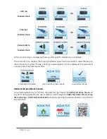
Power-up Sequence
On start up, the controller will run through a diagnostic start-up and the sequence will be dis-
played as follows on the colour LCD:
Next, the controller checks for and initializes any optional modules that may be attached to the
system.
UV Sensor
Module Check
OR
Solenoid
Module Check
OR


