background image

Be sure motor is kept dry and covered.  In mild climate area, when freezing may 
occur, run pump and filter equipment continuously to prevent freezing. 

MOTOR 

Your pump is equipped with a permanently lubricated, maintenance-free, heavy-
duty industrial quality motor especially designed to withstand the heavy-duty 
requirements of swimming pool application.  Wiring connection must agree with 
incoming line voltage.  Improper wiring can cause serious injuries and damage to 
the motor, voiding warranty. 

NOTE:

  Your motor is designed to withstand the effects of normal rainfall.  To 

increase the life of your motor, observe the following: 
1.)  Do not flood motor or submerge in water.  To do so voids warranty. 
2.)  Provide ample cross ventilation, minimum of 6” at all points. 
3.)  Keep motor and surrounding area clean. 
4.)  Avoid sweeping or stirring dust near motor while it is running. 
5.)  Avoid storing or spilling dry chemicals, powders, etc., near motor. 
6.)  Provide protection against the elements. 
7.)  Locate motor on a slight elevation so water will drain away from motor.  
8.)  Avoid spilling or dripping liquid chemical on or near motor. 
9.)  Avoid splashing water or hosing deck near motor.  Water damage voids 

warranty. 

 
For replacements, contact your local supplier or authorized service center. 
 

WARNING - All electrical wiring of the motor installation must be done by a 
qualified electrician in accordance with applicable electrical codes.  Before 
working on any motor, be certain that the source of electrical power is off 
at the main junction box. 
BONDING WIRE - Upon installation of the pump, the motor must be bonded 
with (no smaller than) a No. 8 AWG solid copper conductor per National 
Electrical Code.  The connection should be from the accessible wire 
connector on the motor to all metal parts of the swimming pool, spa or hot 
tub structure and to all electrical equipment, metal conduit, and metal 
piping within 6 feet (1.5 m) of the inside walls of a swimming pool, spa or 
hot tub, when the motor is installed within 5 feet of the inside walls of the 
swimming pool, spa, or hot tub. 
NOTE:  For electrical connections, see wiring diagram on motor rating 
plate. 


Summary of Contents for "A" Series & "LEA" Series Pumps A Series

Page 1: ...rmanently installed pools and may also be used with hot tubs and spas if so marked Do not use with storable pools A permanently installed pool is constructed in or on the ground or in a building such that it cannot be readily disassembled for storage A storable pool is constructed so that it may be readily disassembled for storage and reassembled to its original integrity and has a maximum dimensi...

Page 2: ...t up pump must be primed by filling hair and lint trap with water To prime pump remove cover from hair and lint trap fill pump and suction trap with water Replace cover make sure the o ring is in place and tighten lock handles Pump will now prime with priming time depending upon lift and horizontal distance of suction piping CAUTION Do not remove hair and lint strainer lid while pump is running or...

Page 3: ... elements 7 Locate motor on a slight elevation so water will drain away from motor 8 Avoid spilling or dripping liquid chemical on or near motor 9 Avoid splashing water or hosing deck near motor Water damage voids warranty For replacements contact your local supplier or authorized service center WARNING All electrical wiring of the motor installation must be done by a qualified electrician in acco...

Page 4: ...ce of volute Not pumping water check Worn or damaged impeller Circuit breakers Incorrect or loose wire connections Motor does not run check Thermal protector in motor tripped Allow motor to cool then try to restart Make sure motor shaft turns free Jammed impeller or an obstruction in volute casing Motor makes humming noise but won t start check Low voltage and undersized wire Incorrect or loose wi...

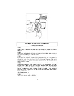
Page 5: ...ft keyway Align pump bracket holes with threaded holes on motor and install four 3 8 16 hexbolts and tighten with 9 16 wrench STEP 4 Place assembled pump in its normal position on the pump base To adjust impeller place screwdriver on the pump shaft as shown and gently pry pump shaft towards motor 015 inches and tighten one set screw with 1 8 Allen wrench Rotate shaft to check if impeller is clear ...

Page 6: ...ge Less Foot 10 10 92770150 92770150 Volute 3 0 HP Volute 3 0 HP 10A 10A 92770200 92770200 Volute 33 2 0 HP 100 Drain 11 11 91100100 91100100 Base Plastic Base Plastic 12 12 99050110 99050110 Bolt Hex Machine 5 16 18 x 1 Bolt Hex Machine 5 16 18 x 1 13 13 99890050 99890050 Washer Lock 5 16 Washer Lock 5 16 14 14 92290000 92290000 Plug Pipe Plug Pipe 15 15 91500150 91500150 Gasket Trap 5 Gasket Tra...

Page 7: ...DIAGRAM Please Refer to table located on page 6 AQUA FLO LLC P O BOX 2526 CHINO CALIFORNIA 91708 SHIPPING 5651 SCHAEFER AVENUE CHINO CALIFORNIA 91710 TEL 909 591 7453 FAX 909 627 5660 WWW AQUA FLO COM 7 ...

Page 8: ...ee through five any such products shall prove defective the original retail purchaser shall be entitled to purchase replacement equipment or components at the following percentage off the current published list price Third year 60 Fourth year 40 Fifth year 20 1 This warranty shall not apply to any failures resulting from negligence abuse misuse misapplication improper installation alteration or mo...

Reviews: