background image

MULTISWITCH

4. Connecting external components

4. Connecting external components

4. Connecting external components

4. Connecting external components

4.1. Overview

4.1. Overview

4.1. Overview

4.1. Overview

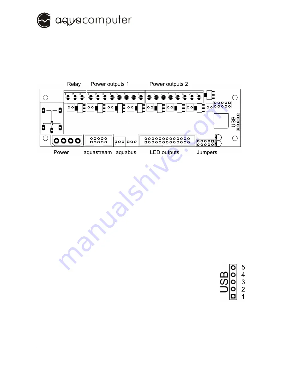
The following schematic shows the multitude of connection possibilities 
of the multiswitch™:

4.2. Power connector

4.2. Power connector

4.2. Power connector

4.2. Power connector

Attach a vacant power connector of your PSU. Due to the form of the 
plug the polarity can not be misinterpreted. Do not use force when 
connecting the plug but double check if the plug is lined-up correctly 
(i.e. not upside down)
Pinassignment: Pin 1: +12 V

Pin 2: GND
Pin 3: GND
Pin 4: +5 V

4.3. USB

4.3. USB

4.3. USB

4.3. USB

Connection possibility for an internal USB-connector on the 
mainboard. Use the included USB-cable and pay close 
attention to the polarity (colored wires) of the cable. Incorrect

Incorrect

Incorrect

Incorrect    

use may result in the destruction of the aquaero and/or the

use may result in the destruction of the aquaero and/or the

use may result in the destruction of the aquaero and/or the

use may result in the destruction of the aquaero and/or the    
mainboard and further components

mainboard and further components

mainboard and further components

mainboard and further components!!!! Therefore pay close 
attention to the pin assignment of the connectors on the mainboard. 
Please consult the manual of your mainboard for help.
Pin assignment: 

Pin 1: GND

black wire

Pin 2: GND

black wire

© 2005-2012

Aqua Computer GmbH & Co. KG

- 5 -

Gelliehäuser Str. 1, 37130 Gleichen

Summary of Contents for multiswitch 1.41

Page 1: ...Manual multiswitch 1 41 Firmware Version 1 06 OS Version 1 02 The information contained in this manual is subject to change without prior notice All rights reserved Current as of Juli 19th 2012 2005 2...

Page 2: ...mpers 6 4 6 Power outputs 1 2 6 4 7 LED outputs 7 4 8 Relay 8 4 9 aquastream 8 5 Configuration 9 Jumper position 1 aquabus address 9 Jumper position 2 Save configuration 9 Jumper position 3 Deactivate...

Page 3: ...e from materials of the highest quality We hope you enjoy your new cooling system Should you have any questions we would like to ask you to first look at the FAQ area and forum on our homepage www aqu...

Page 4: ...e must not exceed 1 Ampere must not exceed 1 Ampere must not exceed 1 Ampere 8 All statements in this manual are subject to the fast 8 All statements in this manual are subject to the fast 8 All state...

Page 5: ...4 3 USB 4 3 USB Connection possibility for an internal USB connector on the mainboard Use the included USB cable and pay close attention to the polarity colored wires of the cable Incorrect Incorrect...

Page 6: ...st must must must not not not not be higher than 40 Watts be higher than 40 Watts be higher than 40 Watts be higher than 40 Watts Incorrect use may result in the destruction Incorrect use may result i...

Page 7: ...connecting capacitive and inductive loads appropriate precaution measures must be taken 4 7 LED outputs 4 7 LED outputs 4 7 LED outputs 4 7 LED outputs Connection possibilities for up to eight LEDs Th...

Page 8: ...9 aquastream 4 9 aquastream Connection possibility to the controller of the aquastream A maximum of two aquastream controller may be connected The following chart shows the connection possibilities d...

Page 9: ...er position 2 Save configuration Jumper position 2 Save configuration Jumper position 2 Save configuration When this jumper is set the current condition of the outputs are saved with each keypress sup...

Page 10: ...h buttons When the jumper is set the condition on off of the corresponding power output is switched Additionally the outputs may be switched via the PC software if the multiswitch is connected via USB...

Page 11: ...ve contact to parts of the PC case Now configure the functions of the multiswitch as described in chapter 5 Configuration Make all desired connections to the multiswitch as described in chapter 4 Conn...

Page 12: ...ded in delivery To do this simply unscrew the four mounting screws in the corners change the front plate and carefully retighten the screws 8 Technical Data 8 Technical Data 8 Technical Data 8 Technic...

Reviews: