Aprilaire 8870 System Installation Manual Download Page 14

12

IMPORTANT!

THESE STEPS MUST BE DONE AT EACH THERMOSTAT 

FOR COMMUNICATION TO WORK PROPERLY.

1. Press the 

Mode

and 

Enter

buttons simultaneously

through the thermostat. It may take a couple of tries to
get them pressed together.

This will enter the Thermostat Set Up Menu. The first
menu item that will appear on the message center display
is an informational item that indicates that only the 

Scroll Up, Scroll Down

(two buttons located immediately

to the right of the message center display) and the 

Enter

buttons are used in thermostat set up. This will

remain on the display for approximately 5 seconds or until
any of the three aforementioned buttons is pressed.
Thermostat Set Up is a series of sub-menus available to
customize the thermostat in various ways. The thermostat
Owners Manual and Installation Manual outline the
thermostat set up features. The following steps will guide
only through the Communications Set Up sub-menu 
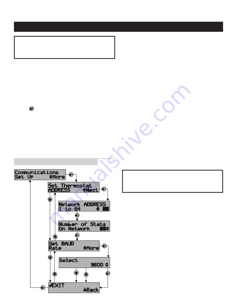
(see 

ILLUSTRATION 5

).

2. Press the 

Scroll Down

button until the “Communications

Set Up” menu shows on the display.

3. Press the 

Enter

button to select this sub-menu.

4. The first sub-menu item is “Set Thermostat ADDRESS”.

Press the 

Enter

button to select this item.

5. Set the address between 1 and 64 using the 

Scroll Up

and 

Scroll Down

buttons. (If using Model 8840

thermostats, see Appendix 1.)

• Each thermostat must have a unique address 

(i.e. no two thermostats can have the same address)

• Start with address 1 and increment by 1 for each new

address – do not skip an address. This will help to
speed communications.

Write down the address for each thermostat 

on the Network Interconnection Worksheet 
(see ILLUSTRATION 3).

6. After the address has been selected, press the 

Enter

button to store the address.

7. Use the 

Scroll Up

and 

Scroll Down

buttons to set the

“Number of Stats On Network” to the highest address
that will be on the thermostat network. This will be equal
to the total number of thermostats on the network, unless
one or more addresses are skipped.

IMPORTANT!

THIS NUMBER MUST BE SET THE SAME 

AT EACH THERMOSTAT

8. After setting the number of thermostats on the network

press 

Enter

. The next item will be to “Set BAUD Rate”.

The thermostat defaults to 9600 baud (bits per second).

• If you want to change to 19200 baud operation, 

continue with #9.

• If you want to operate at 9600 baud, press the 

Scroll

Down

button to get to the “EXIT” screen for the

Communications Set Up sub-menu and go to #10.

9. Press 

Enter

to set the baud rate. Use the 

Scroll Up

or

Scroll Down

button to toggle between 9600 baud and

19200 baud. Press 

Enter

when the baud rate desired is

showing.

10. Press 

Enter

to “EXIT” the Communications Set Up

sub-menu. This will return you to the main menu.

11. Press the 

Scroll Down

button until “EXIT” is displayed.

Press the 

Enter

button. The thermostat will then reset and

return to normal operation.

ADDRESS THE THERMOSTATS AND SET HIGHEST ADDRESS

Step 12

ILLUSTRATION 5 – Setting the Thermostat Address

Summary of Contents for 8870

Page 1: ...A P A R T O F T H E A P R I L A I R E I N D O O R A I R C O M F O R T S Y S T E M AUTOMATED HVAC THE BEST IN INDOOR AIR COMFORT Communicating Thermostat System Installation Manual ...

Page 2: ...STEPS INVOLVED IN THE INSTALLATION OF A COMPLETE SYSTEM Step 1 GET ALL THE COMPONENTS YOU WILL NEED 1 Step 2 DISCONNECT POWER TO ALL HVAC EQUIPMENT AND OR ZONE CONTROL PANELS 2 Step 3 RUN THE REQUIRED WIRES 3 Step 4 LOCATE AND MOUNT THE AUTOMATION SYSTEM COMPONENTS 4 Step 5 CONNECT THE CONTROL WIRES TO THE HVAC ZONE SYSTEM AND THERMOSTATS 6 Step 6 CONNECT THE COMMUNICATION AND POWER WIRES TO THE D...

Page 3: ...A B A B A B A B A B A B A B MAIN PWR ON OFF R C 24VAC FUSE SPARE FUSE R C A A B B R C A A B B R C A A B B R C A A B B 1 COMPONENTS YOU WILL NEED see ILLUSTRATION 1 One Aprilaire Model 8870 Communicating Thermostat for each zone or single zone HVAC system One Aprilaire Model 8818 Distribution Panel per eight 8 thermostats in the system One Aprilaire Model 8811 Protocol Adapter per 32 thermostats or...

Page 4: ... to support two sensors The Model 8061 has one onboard temperature sensor and room for one offboard temperature sensor sensor 1 sensor 2 while the Model 8062 has one onboard temperature sensor sensor 1 and one onboard humidity sensor sensor 2 All sensors can be configured as either a control sensor replaces thermostat temperature sensor as control variable or a monitor sensor read only An offboard...

Page 5: ...ION 2 Step 3 1 Run thermostat cable from each thermostat to the appropriate HVAC system or zone control panel Use 4 through 8 conductor thermostat cable depending on the type of equipment and number of equipment stages Run one more wire than would be required if connecting to a mechanical thermostat If you are using remote temperature or humidity support modules as part of your installation now is...

Page 6: ...ME DURING THE REST OF THE INSTALLATION 2 Mount the zone control panel s if the HVAC system s is zoned Refer to the zone control panel installation instructions 3 The Aprilaire Distribution Panel must be mounted indoors in an accessible location such as a closet or utility room All thermostats will be wired to the Distribution Panel so adequate workspace will be important There are wire access hole...

Page 7: ...ION PANEL LOCATION NAME DISTRIBUTION PANEL TO DISTRIBUTION PANEL CAT 5 WIRE CAT 5 WIRE CAT 5 WIRE CAT 5 WIRE CAT 5 WIRE CAT 5 WIRE CAT 5 WIRE CAT 5 WIRE CAT 5 WIRE CAT 5 WIRE Fill Out and Leave with System Software Package RX TX DATA RS 232 RX TX ENABLE RS 485 RX TX DATA RS 485 POWER Model 8811 Protocol Adapter Power 7 5VAC RS 485 RS 485 RS 232 5 ILLUSTRATION 3 Network Interconnection Worksheet ...

Page 8: ... SHEET FOR INTERNAL SCHEMATIC THERMOSTAT CHECK OUT PROCEDURES AND OTHER HVAC WIRING DETAILS R V Heat B R V Heat B DEH Y1 HUM W1 RC RH G W2 C RSC RSA RSB RSR R REF Y2 B B A A CAUTION ENSURE HVAC SYSTEM POWER IS OFF BEFORE WIRING USE 18 20 GA THERMOSTAT CABLE NUMBER OF CONDUCTORS REQUIRED DEPENDS ON THE HVAC SYSTEM BEING CONTROLLED REFER TO THE THERMOSTAT INSTALLATION SHEET FOR INTERNAL SCHEMATIC TH...

Page 9: ...l 8027 PLUG IN TRANSFORMER Model 8818 DISTRIBUTION PANEL RX TX DATA RS 232 RX TX ENABLE RS 485 RX TX DATA RS 485 POWER Model 8811 Protocol Adapter Power 7 5VAC RS 485 RS 485 RS 232 A A A CAT 5 CAT 5 CAT 5 CAT 5 DEH Y1 HUM W1 DEH Y1 HUM W1 DEH Y1 HUM W1 R V Cool O R V Cool O R V Heat B R V Heat B R V Cool O R V Cool O R V Heat B R V Heat B R V Cool O R V Cool O R V Heat B R V Heat B B B REF A R C A...

Page 10: ...enerating devices such as in an industrial or office setting CAT 5 See NOTE ON REF WIRE DEH Y1 HUM W1 R V Cool O R V Cool O R V Heat B R V Heat B 8 1 MAKE SURE THAT ALL SWITCHES IN THE DISTRIBUTION PANEL ARE OFF 2 Connect the communication wires DIAGRAM 4 shows how each thermostat is to be wired to the distribution panel Use the wire colors shown in DIAGRAM 4 to help ensure proper consistent conne...

Page 11: ...WER Model 8811 Protocol Adapter Power 7 5VAC RS 485 RS 485 RS 232 B B REF A R C A A B B A B A OFF ON OFF ON ON OFF ON OFF PWR PWR A B A B R C A A B B B B REF A R C A A B B A B A OFF ON OFF ON ON OFF ON OFF PWR PWR A B A B R C A A B B DISTRIBUTION PANEL 1 DISTRIBUTION PANEL 2 9 1 MAKE SURE THAT ALL SWITCHES IN THE DISTRIBUTION PANEL ARE OFF 2 If more than one Distribution Panel is used in the therm...

Page 12: ... ON OFF ON ON OFF ON OFF PWR PWR A B A B R C A A B B DISTRIBUTION PANEL RJ 11 RJ 11 1 2 3 4 5 6 CONNECTOR END VIEW 1 MAKE SURE THAT ALL SWITCHES IN THE DISTRIBUTION PANEL ARE OFF 2 Use Category 5 wire to connect the main communication terminals on the Distribution Panel with the Flying Leads of the protocol adapter see DIAGRAM 6 3 Connect the RS 232 port of the protocol adapter to the computer or ...

Page 13: ...power switch then turn on the power switch to one of the thermostats see ILLUSTRATION 4 The green LED next to the power switch should go on and the corresponding thermostat display should power up DO NOT TURN ON ANY OTHER SWITCHES 4 One by one turn on only the power switches not the communication switches for each thermostat Verify that the green LED comes on and that the thermostat display powers...

Page 14: ...s i e no two thermostats can have the same address Start with address 1 and increment by 1 for each new address do not skip an address This will help to speed communications Write down the address for each thermostat on the Network Interconnection Worksheet see ILLUSTRATION 3 6 After the address has been selected press the Enter button to store the address 7 Use the Scroll Up and Scroll Down butto...

Page 15: ... If the COMMUNICATIONS or HYPERTERMINAL folder is not present you will need to add this program to your Windows setup From the Start menu select SETTINGS CONTROL PANEL then select double click the Add Remove Programs icon Select the Windows Setup tab and place a in the Communications component box This will add HyperTerminal to your Windows setup Go back to 3 and get into the HyperTerminal folder ...

Page 16: ...st available number if you are unsure which one to use Click OK 7 A COM1 Properties dialog box should appear Use the pull down menus or type in the following for each selection see ILLUSTRATION 9 Bits per second 9600 or 19200 if thermostats are configured for this baud rate Data bits 8 Parity None Stop bits 1 Flow control none Click OK 14 ILLUSTRATION 8 Select Com Port ILLUSTRATION 9 Connection Pr...

Page 17: ...er keyboard Type any character and confirm that the RS 485 Data TX LED and the RS 232 Data RX LED see DIAGRAM 6 on page 10 on the Protocol Adapter flash as you type The LEDs flash very quickly 13 Press Enter to clear the command line Note On Windows 98 computers HyperTerminal does not echo typed characters doesn t show them on the screen as you type locally Do not be concerned This can be a little...

Page 18: ...not exactly as shown there is a communication signal problem The most likely sources are a loose terminal connection incorrect wire type damaged wire electrical interference or incorrect power supply Look at all the terminal connections and look at the wire where the insulation was stripped If the wire appears kinked trim the wire and carefully strip the insulation Also make sure the wires connect...

Page 19: ...l 8870 thermostat to a system using 8840 series thermostats 8844 8846 8847 or 8848 you must change the power supply installation modify the addressing method and remove terminating resistors from the Model 8811 protocol adapter 1 A separate power supply is required for Model 8870 thermostats and 8840 series thermostats This requires different wiring If using a Model 8800 8808 Communication Panel s...

Page 20: ...F ON OFF ON OFF ON OFF ON ON OFF ON OFF ON OFF ON OFF PWR PWR PWR PWR A B A B A B A B MAIN PWR ON OFF R C 24VAC FUSE R C A A B B R C A A B B MODEL 8818 DISTRIBUTION PANEL 2 WIRE TSTAT CABLE 2 IMPORTANT When addressing the thermostats the Model 8870 thermostat s must either be the first addresses on the network or there must be one address skipped between 8840 series thermostats For example if one ...

Page 21: ...o set your value Spaces are allowed between the command and the action The final portion Value is used only if a command or variable is to be set The value must follow the action with no intervening spaces A carriage return is used as the terminator for the command string Line feeds LF should not be sent with commands as this is a recognized ASCII character and invalidates any command received bet...

Page 22: ...ue which when added to the current heat set point does not fall outside the SH limits SH Decrement heat set point Integer value which when deducted from the current heat set point does not fall outside the SH limits SC Cool Mode Set Point Two or three digit integer 42 90 for F 6 33 for C SC Increment cool setpoint Integer value which when added to the current cool set point does not fall outside t...

Page 23: ... ADDRESS LOCATION DISTRIBUTION PANEL LOCATION NAME DISTRIBUTION PANEL TO DISTRIBUTION PANEL CAT 5 WIRE CAT 5 WIRE CAT 5 WIRE CAT 5 WIRE CAT 5 WIRE CAT 5 WIRE CAT 5 WIRE CAT 5 WIRE CAT 5 WIRE CAT 5 WIRE Fill Out and Leave with System Software Package RX TX DATA RS 232 RX TX ENABLE RS 485 RX TX DATA RS 485 POWER Model 8811 Protocol Adapter Power 7 5VAC RS 485 RS 485 RS 232 ...

Page 24: ...DP 10005754 1 5 4 02 1015 E WASHINGTON AVE MADISON WI 53703 PHONE 888 782 8638 FAX 608 257 4357 www aprilaire com ...

Reviews: