background image

KP-5600 Se

Step 4 I

(F
pr

Step 5 F
3-h) 

Step 6 Fi

(F


eries Touch

nstall the

Figure 3-

roperly. (

Fig

Fit the top

t the lowe

Figure 3-j

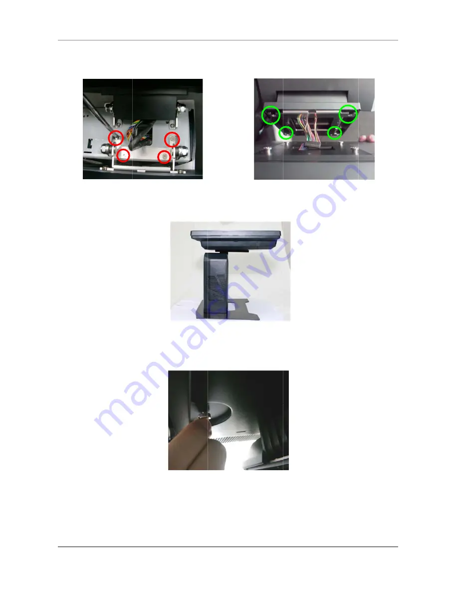
h POS Term

e hinge w

f) Make 

Figure 3-

gure 3-f


p hinge co

er hinge c


minal


with 4 scr

sure tha

g) 

over and 

cover to th

rews. Fit 

at the 4 

the uppe

he second

Figure 3-j

Figure 3

the secon

connect

er hinge c

d display a

3-h 

HARDWA

nd display

ion point

Figure 3

cover of t

and fix wit

RAE INST

y onto th

ts are co

3-g


the panel

th 1 thum

TALLATION

13

he hinge.

onnected 

. (Figure 

mb screw.


All manuals and user guides at all-guides.com

Summary of Contents for KP-5660

Page 1: ...c User Edition A 566 566 ch PO r s M Apr 2014 60 K 64 K OS Ter Manu KP 5 KP 5 rmina ual 566 566 al 62 66 http www appostar com Version m 1 0 All manuals and user guides at all guides com a l l g u i d e s c o m ...

Page 2: ...g ut where city office product ommiss and found art 15 o protectio pment ge nstalled ful interf that interf does caus be determ try to cor eceiving a etween th to an outl ected xperience 5 of the F use harm t any inte se undes ent osion ens only wit rer al and E he produ of with o waste eq of waste to send y e your h KP 56 sion FC d to comp f the FC n against enerates and used ference t ference w ...

Page 3: ...e right to make improvements to this publication from time to time in the contents hereof without obligation of the manufacturer to notify any person of such revision or changes Copyright This work is copyrighted Reproduction or retransmission of this documentation in whole or in part without prior written permission from the manufacture is a violation of copyright law 2014 APPOSTAR Technology Co ...

Page 4: ...ntaining flammable gas inside or around the product 7 Do not allow foreign objects or liquids to enter the product serious damage may result 8 Do not place the product on an unstable surface The product may cause a fire if it is dropped damaged or broken The following instructions will help you make better use of this product 1 Keep the machine from locations subject to high humidity dust and temp...

Page 5: ...rdware Installation 9 2 1 Peripheral Installation 9 2 2 Component Installation 15 CHAPTER 3 Software Installation 17 3 1 Mainboard Driver Installation 17 3 2 Peripheral Device Driver Installation 19 CHAPTER 4 BOARD SETTING 21 4 1 Main Board Jumper Setting 21 CHAPTER 5 Troubleshooting 23 All manuals and user guides at all guides com ...

Page 6: ...is als one of the wing items act the de 2 Quick 5 vervie is the high nd to bala cost effec gn and roc ance but m data los o provide e operatio s are con ealer from k Referenc Power Co KP 56 ew h perform nce both ctive way ck solid s reasonab ss under ed with fiv on environ ntained in m whom y ce Guide ord 600 Series T mance for the cost but also i tructure m ble price power fa ve color op nments t...

Page 7: ...able manag cover eries Touch pearan View View Base cover gement h POS Term ce minal P PRODUCT O 15 L touc Front Cust disp MS Rear OVERVIEW 3 LCD h panel panel tomer play cover R cover r cover W r All manuals and user guides at all guides com ...

Page 8: ...PRODUCT 4 Side Vi Left Righ T OVERVIEW iew Side ht Side I O with W h cover KP 56 600 Series T I O with Touch POS hout cove S Terminal r All manuals and user guides at all guides com ...

Page 9: ...PRODUCT OVERVIEW KP 5600 Series Touch POS Terminal 5 1 3 I O Interface All manuals and user guides at all guides com ...

Page 10: ...onnector Audio Jack 1 x Line out Audio Jack 1 x Mic in USB USB 2 0 A Type x 1 Speaker 1 5 W passive stereo speaker x 2 Control Interface Power Button Press the Power Button to turn the POS system ON OFF The Power LED Indicator will display the current power status of the POS system Reset Button Press to restart your system Power LED Indication Indicates the power ON OFF status Green System is powe...

Page 11: ... Interface Serial Port 4 x External COM Ports with 5V 12V selectable 500mA Cash Drawer Port 1 x RJ11 with DC 12V Default 24V Keyboard Port 1 x PS 2 Keyboard or Mouse VGA Port 1 x DB15 VGA Audio Jack 1 x Mic in 1 x Line out Speaker 2 x Integrated 1 5 W stereo speaker Ethernet Port 1 x RJ45 10M 100M 1000M 1G Base T USB Port 3 x USB 2 0 Type A 2 x USB 3 0 Type A DC Output 1 x 12V 2 5A DC Jack Optiona...

Page 12: ...ent EMC Safety CE FCC Class A Operating Temperature 5 C 40 C Storage Temperature 20 C 60 C Operating Humidity 15 80 RH Storage Humidity 20 90 RH Mechanical Housing Color Cool White Dark Gray Construction ABS SECC Dimension W x D x H 400 x 225 x 320 mm Weight N W 8 5 kg All manuals and user guides at all guides com ...

Page 13: ... mod minal ware I are config s disconn llation e Read An o right from the Step ule in po Instal guration nected to er MSR ptional M t left side MSR 2 Connec osition wit llation ensure t o prevent R Inst MSR can b of KP 56 ct the MS th 2 HARDWA n hat the sy t possible allation be installe 600 Series R cable c RAE INST ystem is e damag n ed in both s correctly TALLATION 9 powered e to the h N All ma...

Page 14: ... custom 2 thumb s Figure 2 b roperly p D VFD C mer displa screws of please ref Custom ay cover o ff the rea Figure 2 KP 56 fer to CH mer Disp on the ma r cover by 2 a 600 Series T 5 Troub play Ins ain unit y a coin Figu Touch POS bleshooti stallatio Figure 2 ure 2 c S Terminal ing on 2 b 2 c All manuals and user guides at all guides com ...

Page 15: ...f screw ho h 2 i gure 2 h isplay do g minal splay into Plug the w s shown i oles with p esn t wor o the brac wafer con n the pict plastic lid rk proper ket and t nector to ture Fig ds and rei ly please HARDWA hen fix th the COM ure 2 f Figure 2 Figure 2 nstall the Figure e refer to RAE INST hem onto 6 port wi 2 e 2 g e rear cov 2 i CH 5 TALLATION 11 the main th DC 5V ver N All manuals and user gui...

Page 16: ...n gure 3 d y Instal o its horiz managem the 2 thu igure 3 b nge cover llation zontal po ment and umb scre b 3 c r using a Figure 3 KP 56 sition F the custo ws off bo screwdriv 3 a 600 Series T igure 3 a omer disp th the fro Figure 3 ver Figu Figure 3 Touch POS a play cover ont and re 3 c re 3 d 3 3 e S Terminal rs on the ear cover e All manuals and user guides at all guides com a l l g u i d e s c...

Page 17: ...hinge co er hinge c minal with 4 scr sure tha g over and cover to th rews Fit at the 4 the uppe he second Figure 3 j Figure 3 the secon connect er hinge c d display a 3 h HARDWA nd display ion point Figure 3 cover of t and fix wit RAE INST y onto th ts are co 3 g the panel th 1 thum TALLATION 13 he hinge onnected Figure mb screw N All manuals and user guides at all guides com ...

Page 18: ...ing ATION he VGA ca r output he front 3 m gure 3 l play does g ble to the DC jack the rear n t work e VGA por Figure and the properly Figure 3 KP 56 rt DB15 3 k cable ma please re 3 k 600 Series T and the p nagemen Figure 3 efer to CH Touch POS power cab nt covers 3 m H 6 S Terminal ble to the All manuals and user guides at all guides com ...

Page 19: ...mb sc gure 4 c 4 screws f w one minal allation HDD panel to it mb screw TA 1 and S rew that from the n ts horizon ws off the SATA pow holds the HDD brac Figure 4 Figure 4 ntal positi front cov wer cables e HDD bra cket to re 4 a 4 b HARDWA on Figu ver of the from the acket in p Figure 4 move the RAE INST ure 4 a e main un e HDD Un place Fig 4 d e HDD and TALLATION 15 it nfasten 1 gure 4 c d replac...

Page 20: ... e Mini PCI ini PCI Ex gure 5 c racket alo igure 4 e ess Card screws of Express xpress ca ong with e 4 f d Instal ff the rea Card Slot rd into th KP 56 the cable llation r cover by t on the m he slot 600 Series T s and the Figure y a coin Figure 5 mother bo Figure 5 Touch POS en the fro 4 f Figure 5 5 b oard Fig 5 d S Terminal ont cover 5 a 5 b gure 5 d All manuals and user guides at all guides co...

Page 21: ...ar Driver Installer appears on the screen If not locate the Setup exe file at CD and double click it to execute the one step driver installation Follow the on screen instructions to complete the installation 3 1 Mainboard Driver Installation a Please select your model name and click NEXT to continue b Click Drivers icon on the upper left corner to continue c Select the Drivers option Click Install...

Page 22: ...lect Install this driver software anyway in Windows Security window to continue the installation procedure g Select Install in Windows Security window to continue the installation procedure h Select Yes to reboot system All manuals and user guides at all guides com ...

Page 23: ... a Click Peripheral Devices b Click Touch Panel c Click Next on the Welcome screen to continue d Uncheck the Install PS 2 interface driver option Click Next to continue e Select the Install RS232 interface driver option Click Next to continue f Select the None option and click Next to continue All manuals and user guides at all guides com ...

Page 24: ... option Click Next to continue h Select the Destination Folder or use the default one listed i Type a Folder name or use the default one listed Click Next to continue j A progress window appears Please wait k Click Yes The installation completes in seconds All manuals and user guides at all guides com ...

Page 25: ...the jumper to Pin 2 3 close 3 Wait for five seconds 4 Set the jumper to Pin 1 2 close 5 Power on the AC 6 Reset your desired password or clear the CMOS data Serial Port Connectors Headers JSEL1 JSEL2 RS 232 422 485 Switch Headers for COM1 The headers determine that COM1 belongs to RS 232 Default 422 or 485 JSEL1 1 2 RS 232 3 4 RS 422 5 6 RS 485 JSEL2 RS 232 RS 422 RS 485 1 3 3 5 3 5 2 4 4 6 4 6 7 ...

Page 26: ...e Pin 9 12V JCOM3 JCOM5 JCOM6 Serial Port Headers Pin Assignment Pin Assignment 1 DCD 2 RXD 3 TXD 4 DTR 5 GND 6 DSR 7 RTS 8 CTS 9 0V 5V 12V 10 NA JPC3 JPC5 JPC6 Serial Port Voltage Switch Jumper for JCOM3 JCOM5 JCOM6 Pin 1 2 Close Pin 9 0V Default Pin 3 4 Close Pin 9 5V Pin 5 6 Close Pin 9 12V All manuals and user guides at all guides com a l l g u i d e s c o m ...

Page 27: ... standby reset the system If the problem remains unsolved contact your dealer for further assistance The Touch Panel is not working properly 1 Check whether the Touch Panel driver has been correctly installed in the PC If not reinstall and test again 2 If the touch panel can detect the finger touch but the cursor is drifting use the touch tool from Driver CD to execute calibration or draw test Int...

Page 28: ... desktop and click Properties 2 Select the Settings tab and you will see monitor 1 and monitor 2 3 Click monitor 2 and then click Extend my Windows desktop onto this monitor The system turns to be unstable after updating BIOS Press F3 during POST to load the default configuration values for the current menu NOTE If the problem goes beyond the scope of this manual or remains unresolved DO NOT repai...

Reviews: