background image


S-Boom Operation Manual


CAT-0303-8000/3 

__________________________________________________________________________________________________________


__________________________________________________________________________________________________________


Page 

5

 of 

26


1.  Introduction to the S-Boom System


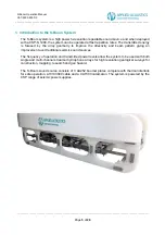
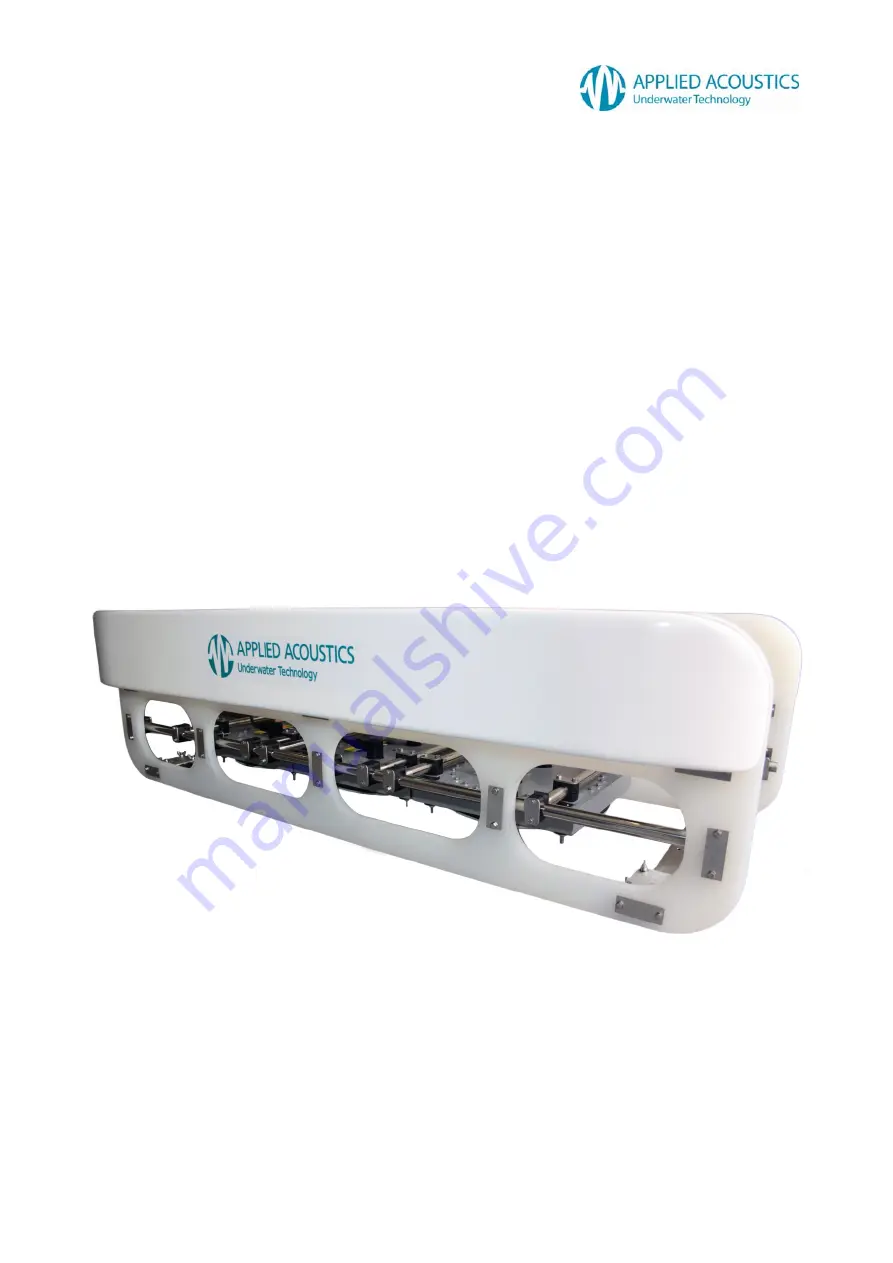
The S-Boom system is a high power hi-resolution repeatable sound source and when deployed 
with a CSP-S 1200, the system can be operated at fast repetition rates. The transmitted energy 
is focused by the array geometry to improve the directivity and beam pattern giving an 
improvement over traditional seismic sound sources.  


The frequency of operation and transmitted power levels allow the system to be used with both 
single and multi-channel streamer hydrophone arrays for high resolution geological surveys for 
construction, mapping, research and geo hazard.  


The S-Boom sound source consists of 3 AA252 boomer plates complete with thermal interlock 
for safe operation, a HVC3000 cable and a CAT303 catamaran. The system is powered by the 
CSP range of seismic power supplies. 


Summary of Contents for S-Boom System

Page 1: ...S Boom System Operation Manual ...

Page 2: ..._______________________ Page 2 of 26 Revision History Issue Change No Reason for change Date A N A Draft 19 12 11 1 1158 Junction box layout and interlock wiring added Amend interlock splice HV3000 cable 27 06 12 2 1300 Addition of recommended lifting arrangement for the CAT303 Drawing updates 14 03 13 3 1416 New boomer plate model AA252 added Addition of negative connection HV Junction Box plates...

Page 3: ...T 14 HVJ3000 JUNCTION BOX BUZZ BAR ARRANGEMENT 15 S BOOM TRIPLE BOOMER ARRANGEMENT POSITIVE CONNECTION 15 DOUBLE BOOMER ARRANGEMENT POSITIVE CONNECTION 15 SINGLE BOOMER ARRANGEMENT POSITIVE CONNECTION 16 TRIPLE BOOMER ARRANGEMENT NEGATIVE CONNECTION 16 DOUBLE BOOMER ARRANGEMENT NEGATIVE CONNECTION 17 SINGLE BOOMER ARRANGEMENT NEGATIVE CONNECTION 17 8 CABLING 18 HVJ3000 JUNCTION BOX INTERLOCK WIRIN...

Page 4: ... Tel 44 0 1493 440355 Fax 44 0 1493 440720 Email techsupport appliedacoustics com Applied Acoustic Engineering Ltd has made every effort to ensure that the information contained in this manual is correct at time of print However our policy of continual product improvement means that we cannot assume liability for any errors which may occur These written instructions must be followed fully for reli...

Page 5: ...ted at fast repetition rates The transmitted energy is focused by the array geometry to improve the directivity and beam pattern giving an improvement over traditional seismic sound sources The frequency of operation and transmitted power levels allow the system to be used with both single and multi channel streamer hydrophone arrays for high resolution geological surveys for construction mapping ...

Page 6: ...ic disc situated behind a diaphragm Energy contained in the electrical storage capacitors in the CSP unit is discharged into the Boomer plate coil This creates a mechanical response on the diaphragm plate due to eddy currents on the plate The resultant acoustic pressure pulse is broad spectrum in nature The Acoustic Pulse shape and reverberation is controlled by damping springs Using a single CSP ...

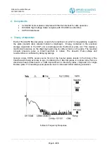
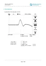
Page 7: ..._______________________________ __________________________________________________________________________________________________________ Page 7 of 26 4 Pulse Signature Typical S Boom Pulse Signature at 1000J Pulse Width 300 uSec V peak to peak 2 7 V Source Level 1 34462 V Bar At 2 5M 222 572 dB re 1 0V uPa At 2 5M ...

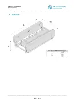
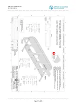
Page 8: ... __________________________________________________________________________________________________________ __________________________________________________________________________________________________________ Page 8 of 26 5 Dimensions ...

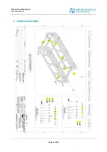
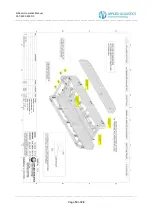
Page 9: ..._______________________________________________________________________________________________________ __________________________________________________________________________________________________________ Page 9 of 26 6 Catamaran Assembly ...

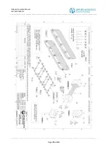
Page 10: ...8000 3 __________________________________________________________________________________________________________ __________________________________________________________________________________________________________ Page 10 of 26 ...

Page 11: ...8000 3 __________________________________________________________________________________________________________ __________________________________________________________________________________________________________ Page 11 of 26 ...

Page 12: ...8000 3 __________________________________________________________________________________________________________ __________________________________________________________________________________________________________ Page 12 of 26 ...

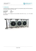
Page 13: ...__________________________________________________________________ Page 13 of 26 7 Configuration The Boomer Plates are configured in a planar array and identified through the HVC3000 cabling to the HVJ3000 Junction Box by colour code Forward AA252 RED Middle AA252 YELLOW Aft AA252 BLUE The S Boom can be configured from the HVJ3000 Junction Box to use 1 2 or 3 of the fitted Boomer plates ...

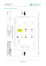
Page 14: ...___________________________________________________________________________________________________ __________________________________________________________________________________________________________ Page 14 of 26 HVJ3000 Junction Box Layout ...

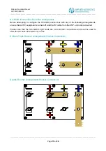
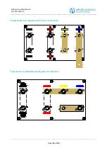
Page 15: ...f 26 HVJ3000 Junction Box Buzz Bar Arrangement Before attempting to configure the HVJ3000 junction box with any of the following arrangements ensure that all HV equipment is turned off and the HV cable from the CSP unit is disconnected Please note that the two bottom right studs are not common connections and must be used to store the HV buzz bars when not in use S Boom Triple Boomer Arrangement P...

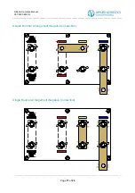
Page 16: ...___________________________________________________________________ __________________________________________________________________________________________________________ Page 16 of 26 Single Boomer Arrangement Positive Connection Triple Boomer Arrangement Negative Connection ...

Page 17: ...___________________________________________________________________ __________________________________________________________________________________________________________ Page 17 of 26 Double Boomer Arrangement Negative Connection Single Boomer Arrangement Negative Connection ...

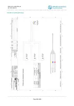
Page 18: ..._________________________________________________________________________________________ __________________________________________________________________________________________________________ Page 18 of 26 8 Cabling HVJ3000 Junction Box Interlock Wiring ...

Page 19: ..._____________________________________________________________________________________________________ __________________________________________________________________________________________________________ Page 19 of 26 Interlock Cabling Subsea ...

Page 20: ...__________________________________________________________________________________________________ __________________________________________________________________________________________________________ Page 20 of 26 AA252 Thermal Interlock Wiring ...

Page 21: ...__________________________________________________________________________________________________________ __________________________________________________________________________________________________________ Page 21 of 26 HVC3000 Cable ...

Page 22: ... stainless shackles on the two points The towropes can provide a degree of steerage by adjusting the tension on each rope The HV Cable Grip should be connected to the tow points and adjusted so that in case of tow rope failure no load is applied to the electrical connections or cable clamp A quick sea trial should be undertaken to check the floatation towing characteristics of the catamaran underw...

Page 23: ...diagram shows the recommended lifting arrangement using 4 lifting eyes in a 4 point lift This arrangement has been tested to the following specification Tare Weight 125kg SWL Weight 75kg Gross Weight 200kg The lifting eyes and any additional lifting accessories used are subject to the end users own country s lifting equipment regulations and should be thoroughly examined at regular intervals For u...

Page 24: ...ic Engineering CAT300 unit does not require regular servicing with the exception above operational inspections NOTE When storing for long periods it is recommended the catamaran is cleaned with fresh water 11 End of Life Recycling Disposal Within the EU all electronic components and batteries must be taken for separate collection at the end of their working life under EU WEEE directives Applied Ac...

Page 25: ...Steel 316 2 spanners supplied AA252 Boomer Overall length 380mm Overall width 380mm Weight 18 Kg Air 10Kg Water Connector RMK c w locking collar HVC3000 Cable Overall length 75m Standard Diameter 26mm Connector RMK c w locking collar Sound Output Source Level Typically 222dB re 1uPa at 2 meters with 1000J Pulse Length 300 to 500uS depending upon energy applied Reverberation 10 of initial pulse Com...

Page 26: ......
Reviews: