background image

23

LIMITED TWO-YEAR WARRANTY

Apollo Gate Operators are warranted against defects for a period of

24 months from the date of purchase, providing recommended installation
procedures are followed. This warranty is in lieu of all other warranties
expressed or implied (some states do not allow limitations on how long an
implied warranty lasts, so this limitation may not apply to you) and shall be
considered void if damage was due to improper installation or use,
connection to improper power source, or if damage was caused by fire,
flood, or lightning. The manufacturer will not be responsible for any labor
charges incurred in the removal or replacement of defective parts.

In case of failure due to defective material or workmanship during the

warranty period, the defective part will be repaired or replaced at the
manufacturer’s option at no charge if returned freight prepaid. New or factory
rebuilt replacements may be used. Replacement parts are warranted for the
remaining portion of the original warranty period. The manufacturer will pay
standard ground freight on the return of repaired or replaced items in
warranty.

APOLLO

Ga t e  Ope ra t ors, I nc .

Summary of Contents for 7200ETL

Page 1: ...Model 7200ETL INSTALLATION MANUAL APOLLO Gate Operators Inc Post Mounted Residential Heavy Duty Commercial Slide Gate Operator 04 11...

Page 2: ...ist 5 Parts Identification 6 Operator Installation 7 Chain Bracket Installation 8 Chain Chain Bolt Installation 8 9 Internal Limits 10 11 Quick Release Operation 12 Programming Current Sensing 13 835...

Page 3: ...rgency access Use the emergency release only when the gate is not moving A secondary entrapment device such as loop detectors edge switches and beam detectors are highly recommended and required to me...

Page 4: ...rs provide up to 200 operations in the event of power outages The battery may be recharged with a trickle charger or by solar energy Electrical battery chargers should have a class 2 transformer ratin...

Page 5: ...ine the general location of the operator chian brackets and solar panel if used 1 Is there a suitable location for the operator 2 Can the solar panel if used be mounted in an unobstructed area facing...

Page 6: ...ps 4 each Master Chain Links 2 each Operator Chain Bolts with hardware 2 each 5 16 x 3 U Bolts 4 each 404C Automatic Battery Charger optional 201 5 Watt Solar Panel Bracket optional 273G CAUTION Signs...

Page 7: ...nside posts 6 STEP 2 Remove chain cover and front lid Mount to posts using the four supplied 3 U bolts STEP 1 Install two 3 dia Posts parallel to the gate as shown Posts height depends on height prefe...

Page 8: ...ate using the supplied 2 U bolts Do not tighten at this time STEP 4 Attach the chain to the chain bolt using the master chain link Adjust the chain bolt to allow for maximum tightening Note The height...

Page 9: ...ed length of chain needed to attach to the chain bolt and still allow adjustment Using a chain breaking tool not provided remove excess chain Attach chain to chain bolt Tighten all chain brackets and...

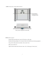
Page 10: ...te moving to the left less travel more travel Limit adjustment for right Movement gate moving to the right less travel more travel Step 4 Adjust the corresponding limit switch for preferred close posi...

Page 11: ...installed on The factory units are plugged into INPUT B for right side installation as shown in Fig 1 For left side installation disconnect from INPUT B and plug into INPUT A on the surge board as sho...

Page 12: ...12 QUICK RELEASE OPERATION Engaged Engaged Pull turn 1 2 inch to disengage...

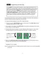
Page 13: ...ce All limits should be set before beginning this procedure This new procedure applies to revision 31 or higher firmware 1 Press and hold the LED ENABLE button for five seconds The STOP LED will blink...

Page 14: ...Indicators Optional Device Input Remote Monitor Outputs and Photo Eye GateLink Connector Microprocessor Timer To Close Dual Gate Delay Current Sensitivity Adjustments Program Switches 835 836 Control...

Page 15: ...835 836 board Connect the relay wires of the accessory as normal COM to GND NO to SAFETY 14 for a safety device When the gate operator begins opening comes off of the closed limits the MAS terminal wi...

Page 16: ...roubleshooting Hold the push button down for five seconds to put the board in program mode RESET Resets the microprocessor Returns processor to last known state OPERATE When depressed activates the ga...

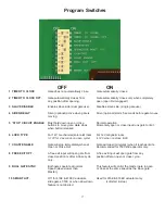
Page 17: ...utton released 6 LOCK TYPE For 12V mechanical solenoid locks For 12V magnetic locks 12V for 4 seconds on open cycle 12V when on close limit 7 COAST ENABLE Gate will stop immediately when at Gate will...

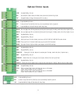
Page 18: ...ion see program switch 5 for options OPEN Open input from a 3 button station see program switch 5 for options GND Supplied Battery Ground GND Supplied Battery Ground FREE EXIT Opens gate if closed sto...

Page 19: ...or on the Remote Monitor Output Connector block Connect the black wire to the GND connector on the Remote Monitor Output Connector block Red Black Set Program Switch 4 as preferred ON Upon activation...

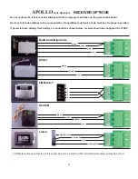
Page 20: ...code switches for proper operation If power is taken directly from battery or connected as shown below receiver should be configured for 12VDC Multi Code Digi Code Allstar Lift Master black gray gray...

Page 21: ...NGLE GATE 1 2 3 5 ON all others OFF DUAL GATE 1 2 5 ON all others OFF 3 LED ENABLE BUTTON On the right side of the board half way down is the LED ENABLE button Pressing this button once and releasing...

Page 22: ...the BLACK and reverse the ORANGE with the WHITE To verify that the wiring has been changed correctly Manually move the gate to the mid way position and plug the main harness into the EMERGENCY BY PAS...

Page 23: ...improper power source or if damage was caused by fire flood or lightning The manufacturer will not be responsible for any labor charges incurred in the removal or replacement of defective parts In ca...

Reviews: