background image

VITAM-9XXA Series User Manual 


69 

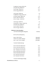
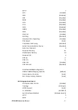
                            PowerDown  Energy  Ch1Dimm0                                                        6 

                            Activate Energy Ch1Dimm0                                                            172 

                            Read  Energy  Ch1Dimm0                                                                212 

                            Write Energy Ch1Dimm0                                                                221 


                            Idle  Energy  Ch1Dimm0                                                                    10 

                            PowerDown  Energy  Ch1Dimm0                                                        6 

                            Activate  Energy  Ch1Dimm0                                                        172 

                            Read  Energy  Ch1Dimm0                                                            212 

                            Write  Energy  Ch1Dimm0                                                        221 


                            Idle  Energy  Ch1Dimm1                                                                    10 

                            PowerDown  Energy  Ch1Dimm1                                                6 

                            Activate Energy Ch1Dimm1                                                            172 

                            Read  Energy  Ch1Dimm1                                                              212 

                            Write  Energy  Ch1Dimm1                                                              221 


Memory Thermal Reporting 

                            Lock Thermal:Management Registers                                    Enabled] 


                            Memory Thermal Reporting 


                            Extern  Therm  Status                                                            [Disabled] 

                            Closed  Loop  Therm  Manage                                              [Disabled] 

                            Open  Loop  Therm  Manage                                             


[Disabled] 


Thermal Threhold Settings 


                            Warm  Threshold  Ch0  Dimm0                                                        255 

                            Warm  Threshold  Ch0  Dimm1                                                        255 

                            Hot  Threshold  Ch0  Dimm0                                                    255 

                            Hot  Threshold  Ch0  Dimm1                                                  255 

                            Warm  Threshold  Ch1  Dimm0                                                        255 

                            Warm  Threshold  Ch1  Dimm1                                                        255 

                            Hot  Threshold  Ch1  Dimm0                                                            255 

                            Hot  Threshold  Ch1  Dimm1                                                            255 


Thermal Throttle Budget Settings 

Summary of Contents for VITAM-9 A Series

Page 1: ...Panel PC User Manual Release Date Revision Jan 2020 V1 7 2020 Aplex Technology Inc All Rights Reserved Published in Taiwan Aplex Technology Inc 15F 1 No 186 Jian Yi Road Zhonghe District New Taipei City 235 Taiwan Tel 886 2 82262881 Fax 886 2 82262883 URL http www aplextec com zh home php ...

Page 2: ... 1 2017 11 07 Add UPS battery 1 2 2018 01 29 Modify OS status High brightness description 1 3 2018 11 01 Modify Operating temperature 1 4 2018 11 23 Revise Backlight Lifetime information 1 5 2019 06 27 Revise1 1 Specification data 1 6 2019 08 06 Add Logistic Statement 1 7 2020 01 02 Revise SBC 7114 Information ...

Page 3: ...rials Electric Shock Hazard Do not operate the machine with its back cover removed There are dangerous high voltages inside This equipment generates uses and can radiate radio frequency energy and if not installed and used in accordance with the instructions manual it may cause interference to radio communications It has been tested and found to comply with the limits for a Class A computing devic...

Page 4: ...VITAM 9XXA Series User Manual 3 Packing List Accessories as ticked included in this package are Adaptor Driver manual CD disc Other ___________________ please specify ...

Page 5: ...city on all occasions Prevent electric shock Don t touch any components of this card when the card is power on Always disconnect power when the system is not in use Disconnect power when you change any hardware devices For instance when you connect a jumper or install any cards a surge of power may damage the electronic components or the whole system ...

Page 6: ...ssure change during transportation This especially applies to air shipment with unpressurized cabin Upon receiving the system please tighten the pressure testing screw before deployment to ensure 100 functionality Here is our suggestion 1 Prepare a 3mm hex screwdriver 2 Tighten the screw indicated in circle clockwise until it is well in place 3 Recommend torque is 8 10 kgf cm Apologies for any inc...

Page 7: ...rd Introduction 16 2 2 Specifications 16 2 3 Jumpers and Connectors Location 20 2 4 Jumpers Setting and Connectors 21 Chapter 3 BIOS Setup 3 1 Operations after POST Screen 58 3 2 BIOS Setup Utility 58 3 3 Main Settings 59 3 4 Advanced Settings 60 3 5 Chipset Settings 69 3 6 Security Settings 92 3 7 Boot Settings 94 3 8 Save Exit Settings 95 Chapter 4 Installation of Drivers 4 1 Intel H170 Chipset ...

Page 8: ...ure 1 4 Dimensions of VITAM 919AP R G H 12 Figure 1 5 Dimensions of VITAM 921AP R G H 13 Figure 1 6 Dimensions of VITAM 924AP G H 13 Figure 1 7 Front View and Touch on off Button of VITAM 9XXA Serie 14 Figure 1 8 Rear View of VITAM 9XXA Series 14 Figure 1 9 Yoke Mounting of VITAM 9XXA Series 15 Figure 1 10 VESA Mounting of VITAM 9XXA Series 15 Figure 2 1 Motherboard Dimensions 19 Figure 2 2 Jumper...

Page 9: ...gienic cleaning Support ergonomic versatile mounting Yoke mounting VESA mounting and Swing arm mounting 1 2 Specifications VITAM 915 AP R G H VITAM 916 AP R G H VITAM 917 AP R G H VITAM 919 AP R G H VITAM 921 AP R G H VITAM 924 AP G H System CPU Intel Core i5 6300U Processor 3M Cache 2 30 GHz Intel Core i3 6100U Processor 3M Cache 2 30 GHz Chipset SoC Memory 1 x 260 pin SO DIMM up to 16GB DDR4 213...

Page 10: ... 1 x M12 for LAN LAN Pin Define 2 LAN1_0 1 LAN1_0 4 LAN1_1 3 LAN1_1 6 LAN1_2 5 LAN1_2 8 LAN1_3 7 LAN1_3 Power 1 x DC power input 9 36V by M12 connector Pin Define 1 NC 3 VCC 4 GND Others 1 x Power Switch on the rear Option I O Port Either two 2 x optional blank M12 connectors with waterproof cap for selecting two from the following options 2 x USB 2 0 ...

Page 11: ...1 3000 1 Viewing Angle 160 H 160 V 160 H 160 V 170 H 170 V 170 H 165 V 178 H 178 V 178 H 178 V Backlight Lifetime 30 000hrs 50 000hrs 50 000hrs 50 000hrs 30 000hrs 30 000 hrs Option Optical bonding Display High Brightness LCD option Display Type 15 TFT LCD 15 6 TFT LCD 17 TFT LCD 19 TFT LCD 21 5 TFT LCD 23 8 TFT LCD Max Resolution 1024 x 768 1366x768 1280 x1024 1280 x1024 1920x1080 1920x1080 Max C...

Page 12: ...ure Mounting VESA mount 75 x 75 Yoke mount VESA mount 100 x 100 Yoke mount VESA mount 200 x 100 Yoke mount IP Rating IP66 IP69K Dimension mm 399 x 324 x 53 440 x 290 x 55 432 x 358 x 55 3 470 x 388 6 x 60 571 x 362 x 55 656 x 423 x 53 Net Weight 7 1 Kg 7 Kg 8 2 Kg 9 5 Kg 10 Kg 12 6 Kg Environmental Operating temperature 0 50 C 0 50 C 0 50 C 0 50 C 0 50 C 0 40 C For High Bright model 0 50 C Storage...

Page 13: ...VITAM 9XXA Series User Manual 12 1 3 Dimensions Figure 1 1 Dimensions of VITAM 915AP R G H Figure 1 2 Dimensions of VITAM 916AP R G H ...

Page 14: ...VITAM 9XXA Series User Manual 13 Figure 1 3 Dimensions of VITAM 917AP R G H Figure 1 4 Dimensions of VITAM 919AP R G H ...

Page 15: ...VITAM 9XXA Series User Manual 14 Figure 1 5 Dimensions of VITAM 921AP R G H Figure 1 6 Dimensions of VITAM 924AP G H ...

Page 16: ...n SO DIMM up to 16GB DDR4L 2133MHz memory and 1 x 2 5 HDD SSD space for storage VITAM 9XXA series is wide range DC 9 36V power input and IP66 IP69K rated with M12 connectors Furthermore the models support resistive touch projected capacitive touch and glass for option and can be high brightness LCD and optical bonding designed for option It supports touch on off button on the side edge for hygieni...

Page 17: ...nual 16 1 5 Yoke Mounting and VESA Mounting The VITAM 9XXA Series model can be Yoke mounted and VESA mounted as shown in Picture below Figure 1 9 Yoke mounting of VITAM 9XXA Series Figure 1 10 VESA mounting of VITAM 9XXA Series ...

Page 18: ...x 113mm CPU Support Intel Core i3 6100U 2 30GHz onboard Intel Core i5 6300U 2 40 up to 3 00GHz option Intel Core i7 6600U 2 60 up to 3 40GHz option Intel Celeron 3955U 2 00GHz option Intel Celeron 3965U 2 20GHz option Intel Core i3 7100U 2 40GHz option Intel Core i5 7300U 2 60 up to 3 50GHz option Intel Core i7 7600U 2 80 up to 3 90GHz option Chipset SOC Memory Support 1x SO DIMM 260pins up to 16G...

Page 19: ... 0 Pin header for EDP1 USB7 or Touch option 1 x USB 2 0 for MPCIE1 USB6 Serial 1 x RS232 RS422 RS485 port DB9 connector for external COM1 Pin 9 w 5V 12V Ring select 1 x RS232 port DB9 connector for external COM2 Pin 9 w 5V 12V Ring select 2 x UART for CN3 COM3 COM4 1 x RS422 485 header for CN2 NCT6106D COM5 1 x RS422 485 header for CN2 NCT6106D COM6 Digital I O 8 bit digital I O by Pin header CN2 ...

Page 20: ...ort Windows 10 IOT Touch Ctrl 1 x Touch ctrl header for TCH1 USB10 Power Management Wide Range DC9V 36V input 1 x 3 pin power input connector Switches and LED Indicators 1 x Power on off switch BT1 BT2 CN2 CN3 1 x Reset CN2 1 x HDD LED status CN2 1 x Power LED status CN1 1 x Buzzer External I O port 2 x COM Ports COM1 COM2 2 x USB 3 0 Ports stack 2 x RJ45 GbE LAN Ports 1 x HDMI Port 1 x Audio Jack...

Page 21: ...VITAM 9XXA Series User Manual 20 Unit mm Figure 2 1 Motherboard Dimensions ...

Page 22: ...VITAM 9XXA Series User Manual 21 2 3 Jumpers and Connectors Location Figure 2 2 Jumpers and Connectors Location Board Top ...

Page 23: ...I7 6600U I7 6600U 2 6 up to 3 4GHz 2 4 15W 25W option SBC 7114 I7 6600UP I7 6600U 2 6 up to 3 4GHz 2 4 15W 25W option SBC 7114 3955U Celeron 3955U 2 0GHz 2 2 15W option SBC 7114 3955UP Celeron 3955U 2 0GHz 2 2 15W option SBC 7114 3965U Celeron 3965U 2 2GHz 2 2 15W option SBC 7114 3965UP Celeron 3965U 2 2GHz 2 2 15W option SBC 7114 I3 7100U I3 7100U 2 40GHz 2 4 15W SBC 7114 I3 7100UP I3 7100U 2 40G...

Page 24: ...under 5W 4 DDR4_1 SO DIMM 260Pin socket DDR4 memory socket the socket is located at the top of the board and supports 260Pin 1 2V DDR4 2133MHz FSB SO DIMM memory module up to 16GB Model DDR4 Memory Types FSB SBC 7114 I3 6100U P 2133 MHz SBC 7114 I5 6300U P 2133 MHz SBC 7114 I7 6600U P 2133 MHz SBC 7114 3955U P 1866 2133 MHz SBC 7114 3965U P 2133 MHz SBC 7114 I3 7100U P 2133 MHz SBC 7114 I5 7300U P...

Page 25: ...Utility to load optimal defaults e After the above operations save changes and exit BIOS Setup 6 S_1 PIN1 Switch ATX Power and Auto Power on jumper setting S 1 Switch Mode Pin1 Off ATX Power Pin1 On Auto Power on Default 7 BAT2 2 0mm Pitch 1x10 Wafer Pin Header smart battery Interface Pin Signal Name Pin1 VCC_BAT1 Pin2 VCC_BAT1 Pin3 VCC_BAT1 Pin4 SMB_DAT_SW Pin5 SMB_CLK_SW Pin6 BAT1_TEMP Pin7 Grou...

Page 26: ... LVDS MCU IC reset Pin Signal Name Pin1 BAT1_LED Pin2 BAT1_LED Pin3 Ground Pin4 SBW_TDIO_RST option 10 DC_IN1 5 08mm Pitch 1x3 Pin Connector DC 9V 36V System power input connector Pin Power Input Pin1 DC_IN DC 9V 36V Pin2 DC_IN Ground Pin3 FG Model DC_IN1 SBC 7114 I3 6100U 180 Connector SBC 7114 I5 6300U 180 Connector SBC 7114 I7 6600U 180 Connector SBC 7114 3955U 180 Connector SBC 7114 3965U 180 ...

Page 27: ...n or awaken the system from sleep state P_SW1 or BT1 need to be selected before manufacturing 2 0mm Pitch 1x2 Wafer Pin Header Power on off button it is used to connect power switch button P_SW1 or BT1 Function BT1 1x2Pin connect Default P_SW1 Button option BT2 Function BT1 1x2Pin connect Default 12 LED2 LED3 LED4 LED5 LED6 LED7 LED8 LED2 LED STATUS Green LED for 3P3V_ALLS_EC Power status LED3 LED...

Page 28: ... of LVDS resolution If you need other resolution settings please upgrade U17 data Model LVDS resolution SBC 7114 I3 6100U P SBC 7114 I5 6300U P SBC 7114 I7 6600U P SBC 7114 I3 7100U P SBC 7114 I5 7300U P SBC 7114 I7 7600U P SBC 7114 3955U P SBC 7114 3965U P 1280 1024 Default 800 480 option 800 600 option 1024 768 option 1920 1080 option 15 INVT1 2 0mm Pitch 1x6 wafer Pin Header Backlight control c...

Page 29: ...OUT 4 3 BKLT_CTRL Ground 6 5 Ground LVDS_VDD5 8 7 LVDS_VDD5 LVDS_VDD3 10 9 LVDS_VDD3 Ground 12 11 Ground LA_D0_P 14 13 LA_D0_N LA_D1_P 16 15 LA_D1_N LA_D2_P 18 17 LA_D2_N LA_D3_P 20 19 LA_D3_N LA_CLKP 22 21 LA_CLKN LB_D0_P 24 23 LB_D0_N LB_D1_P 26 25 LB_D1_N LB_D2_P 28 27 LB_D2_N LB_D3_P 30 29 LB_D3_N LB_CLKP 32 31 LB_CLKN USB7 option Ground 34 33 LCD_EDID_SEN USB7_P 36 35 USB7_N 5V_S5_USB 38 37 L...

Page 30: ...N 20 19 DDI1_TX0_N DDI1_TX2_P 22 21 DDI1_TX0_P Ground 24 23 Ground DDI_TX3_N 26 25 DDI1_AUX_N DDI_TX3_P 28 27 DDI1_AUX_P NC 30 29 I2C1_SCL I2C EDP_HP_CN 32 31 I2C1_SDA Ground 34 33 Ground USB7 option USB7 option USB7_P 36 35 USB7_N 5V_S5_USB 38 37 5V_S5_USB Power LED PWR_LED 40 39 Ground Power LED 19 JP3 S_1 PIN5 2 0mm Pitch 2x2 wafer Pin Header touch jumper setting JP3 Touch TCH1 Open 3 4 default...

Page 31: ... JP1 2 0mm Pitch 2x3 Pin Header COM1 jumper setting pin 1 6 are used to select signal out of pin 9 of COM1 port JP1 Pin Function Close 1 2 COM1 RI Ring Indicator default Close 3 4 COM1 Pin9 DC 5V option Close 5 6 COM1 Pin9 DC 12V option 23 COM1 Type DB9M Rear serial port standard DB9 Male serial port is provided to make a direct connection to serial devices COM1 port is controlled by pins No 1 6 o...

Page 32: ... Request To Send 8 CTS Clear To Send 9 JP1 select Setting RI 5V 12V BIOS Setup Advanced NCT6106D Super IO Configuration F75111 COM1 Configuration RS 232 RS422 option Pin Signal Name 1 422_TX 2 422_TX 3 422_RX 4 422_RX 5 Ground 6 NC 7 NC 8 NC 9 NC BIOS Setup Advanced NCT6106D Super IO Configuration F75111 COM1 Configuration RS 422 RS485 option Pin Signal Name 1 485 2 485 3 NC 4 NC 5 Ground ...

Page 33: ...e 3 4 COM2 Pin9 DC 5V option Close 5 6 COM2 Pin9 DC 12V option 25 COM2 Type DB9M Rear serial port standard DB9 Male serial port is provided to make a direct connection to serial devices Pin Signal Name 1 DCD Data Carrier Detect 2 RXD Received Data 3 TXD Transmit Data 4 DTR Data Terminal Ready 5 Ground 6 DSR Data Set Ready 7 RTS Request To Send 8 CTS Clear To Send 9 JP2 select Setting RI 5V 12V 26 ...

Page 34: ...up to 6 0Gb s 29 S_1 PIN2 Switch MSATA Signal and PCIE Signal jumper setting for MPCIE1 S 1 Switch MPCIE1 Pin2 Off MSATA Signal option Pin2 On PCIE Signal Default 30 MPCIE1 50 95mmx30mm Socket 52Pin mSATA socket it is located at the top it supports mini PCIe devices with LPCbus and SMbus and mSATA signal B2 mSATA bus for flash disk signal Function Support Mini SATA Default S_1 setting Mini PCie Op...

Page 35: ...io port An onboard Realtek ALC269Q codec is used to provide high quality audio I O ports Line Out can be connected to a headphone or amplifier 34 SPK1 2 0mm Pitch 1x4 Wafer Pin Header support a stereo Class D Speaker Amplifier with 2 watt per channel output power Pin Signal Name 1 SPK_OUTL_P 2 SPK_OUTL_N 3 SPK_OUTR_N 4 SPK_OUTR_P 35 USB1 USB3 1 USB3 2 Double stack USB type A Rear USB connector it ...

Page 36: ...N1 6106_GPIO40 6106_GPIO43 GPIO_IN4 6 5 GPIO_IN3 6106_GPIO42 6106_GPIO45 GPIO_OUT2 8 7 GPIO_OUT1 6106_GPIO44 6106_GPIO47 GPIO_OUT4 10 9 GPIO_OUT3 6106_GPIO46 Ground 12 11 Ground 485 or 422 COM5 485 _422TX5 14 13 485 _422TX5 485 or 422 COM5 422_RX5 16 15 422_RX5 485 or 422 COM6 485 _422TX6 18 17 485 _422TX6 485 or 422 COM6 422_RX6 20 19 422_RX6 5V 5V_S0 22 21 HDD_LED HDD LED USB2 0 5V_USB5 24 23 5V...

Page 37: ...s four GPIO two USB 2 0 two PS 2 for keyboard and mouse currently not support two uart one PCIex1 one SMbus two PCIex1 or USB3 0 two USB 2 0 connected to the TB 528 riser Card Function Signal Name Pin Signal Name Function 5V_S5_USB 1 2 5V_S5_USB 5V_S5_USB 3 4 5V_S5_USB USB3489_OC 5 6 PSON_ALL USB4 USB4_N 7 8 USB4_P USB4 USB3 USB3_N 9 10 USB3_P USB3 Ground 11 12 Ground Not support PS2_MSCLK 13 14 P...

Page 38: ...3V_S5 57 58 3P3V_S5 12V 12V_S0 59 60 12V_S0 12V 12V 12V_S0 61 62 12V_S0 12V PCIE3 Ground 63 64 Ground PCIE3 PE3_TX_N0 65 66 PE3_TX_P0 PE3_RX_N0 67 68 PE3_RX_P0 Ground 69 70 Ground CLK_100M_PE0_N 71 72 CLK_100M_PE0_P CLKREQ_PE0 73 74 CLKREQ_PE5 PCIE5 or USB3 0 PCIE5 or USB3 0 Ground 75 76 Ground CLK_100M_PE5_N 77 78 CLK_100M_PE5_P USB5PE1_TX_N 79 80 USB5PE1_TX_P USB5PE1_RX_N 81 82 USB5PE1_RX_P PCIE...

Page 39: ...tandard compliant TPM based on the latest Trusted Computing Group TCG specification 2 0 Note Only support Windows 10 IOT TPM_U1 SLB 9665 TT2 0 MODEL TPM Function SBC 7114 XXX R2 30 SBC 7114 XXX R2 20 X SBC 7114 XXX R1XX X 42 TB 528 series CN3 1 27mm Pitch 2X30 Pin Header connect to SBC 7114 CN2 pin Header M PCIE1 ...

Page 40: ...50 95mm assemble LED1 Mini PCIe devices LED Status SIM1 SIM Socket 6 Pin Support SIM Card devices SIM2 option 1 25mm Pitch 1X6 Pin Wafer for SIM card devices expansion GPIO1 2 0mm Pitch 2x5 Pin Header General purpose input output port it provides a group of self programming interfaces to customers for flexible use Signal Name Pin Pin Signal Name Ground 1 2 GPIO_OUT1 GPIO_OUT2 3 4 SMB_DATA_R SMB_CL...

Page 41: ...ay cause system down and even hardware damages JP5 2 0mm Pitch 2x3 Pin Header COM5 setting jumper pin 1 6 are used to select signal out of pin 9 of COM5 port JP5 Pin Function Close 1 2 RI Ring Indicator default Close 3 4 COM5 Pin9 5V option Close 5 6 COM5 Pin9 12V option COM5 Type DB9 serial port standard DB9 serial port is provided to make a direct connection to serial devices COM5 port is contro...

Page 42: ...ignal Name DCD 1 2 RXD TXD 3 4 DTR Ground 5 6 DSR RTS 7 8 CTS JP6 setting RI 5V 12V 9 10 NC JP6 2 0mm Pitch 2x3 Pin Header COM6 setting jumper pin 1 6 are used to select signal out of pin 9 of COM6 port JP6 Pin Function Close 1 2 RI Ring Indicator default Close 3 4 COM6 Pin9 5V option Close 5 6 COM6 Pin9 12V option COM6 Type DB9 serial port standard DB9 serial port is provided to make a direct con...

Page 43: ...It can be used directly via COM cable connection Signal Name Pin Pin Signal Name DCD 1 2 RXD TXD 3 4 DTR Ground 5 6 DSR RTS 7 8 CTS JP6 Setting RI 5V 12V 9 10 NC PS_ON1 2 0mm Pitch 1x2 Pin Wafer ATX Power and Auto Power on jumper setting PS_ON Mode Close 1 2 Auto Power on default Close 1 2 ATX Power PS_ON2 option 2 0mm Pitch 1x2 Pin Wafer S1 PWR BT POWER on off Button it is used to connect power s...

Page 44: ...Header connect to SBC 7114 CN3 pin Header M PCIE1 Socket 52Pin mini PCIe socket it is located at the top it supports mini PCIe devices with SMbus USB2 0 SIM and PCIe signal MPCIe card size is 30x30mm or 30x50 95mm Signal Name Function support PCIe 1x Yes USB2 0 USB2 Yes SMBus Yes SIM Yes H1 H2 MPCIE1 SCREW HOLES H2 for mini PCIE card 30mm x 30mm assemble H1 for mini PCIE card 30mm x 50 95mm assemb...

Page 45: ... 0mm Pitch 2x5 Pin Header Front USB connector it provides two USB port via a dedicated USB cable speed up to 480Mb s Signal Name Pin Pin Signal Name 5V_USB34 1 2 5V_USB34 NC USB4_N 3 4 NC USB3_N NC USB4_P 5 6 NC USB3_P Ground 7 8 Ground NC 9 10 Ground Note Before connection make sure that pinout of the USB cable is in accordance with that of the said tables Any inconformity may cause system down a...

Page 46: ... provided It can be used directly via COM cable connection Signal Name Pin Pin Signal Name DCD 1 2 RXD TXD 3 4 DTR Ground 5 6 DSR RTS 7 8 CTS JP6 Setting RI 5V 12V 9 10 NC COM5 SBC 7114 COM3 2 0mm Pitch 2X5 Pin Header COM5 Port up to one standard RS232 port is provided It can be used directly via COM cable connection Signal Name Pin Pin Signal Name DCD 1 2 RXD TXD 3 4 DTR Ground 5 6 DSR RTS 7 8 CT...

Page 47: ... bus Signal L 2 R2 Terminal resistor R internally connected to CANL2 3 FG Shield cable FG 4 R2 Terminal resistor R internally connected to CANH2 5 CANH2 CAN bus Signal H 6 CAN1 CANL1 CAN bus Signal L 7 R1 Terminal resistor R internally connected to CANL1 8 FG Shield cable FG 9 R1 Terminal resistor R internally connected to CANH1 10 CANH1 CAN bus Signal H See TB 528CAN2 Manual 44 TB 528E1U2 TB528E1...

Page 48: ...ts speed up to 480Mb s LAN1 RJ45 Connector Rear LAN port one standard 10 100 1000M RJ 45 Ehternet port is provided Use Intel I211 AT chipset LINK LED green and ACTIVE LED green respectively located at the left hand side of the Ethernet port indicate the activity and transmission state of LAN PSE Function support PSE output voltage DC44 57V U2 U7 option For onboard POE powered device module 12V_OUT...

Page 49: ...12V_OUT3 option 2 0mm Pitch 1x6 Pin Header Reserve 12V_OUT1 option 3 96mm Pitch 1x2 Pin Header Reserve JP3 option 2 0mm Pitch 1x3 Pin Header Reserve S1 option Reserve 45 TB 548 R1 00 option SBC 7114 Riser Card TB 548 LVDS1 connects to SBC 7114 CN1 DF13 40P TB 548 INVT1 connects to SBC 7114 INVT1 TB 548 TCH1 connects to SBC 7114 TCH1 TB 548 CON1 connects to TB 547 CON1 TB 548 Top ...

Page 50: ... LVDS_VDD5 LVDS_VDD3 10 9 LVDS_VDD3 Ground 12 11 Ground LA_D0_P 14 13 LA_D0_N LA_D1_P 16 15 LA_D1_N LA_D2_P 18 17 LA_D2_N LA_D3_P 20 19 LA_D3_N LA_CLKP 22 21 LA_CLKN LB_D0_P 24 23 LB_D0_N LB_D1_P 26 25 LB_D1_N LB_D2_P 28 27 LB_D2_N LB_D3_P 30 29 LB_D3_N LB_CLKP 32 31 LB_CLKN USB7 option Ground 34 33 SEL_LCD_EDID USB7_P 36 35 USB7_N 5V_S5_USB 38 37 LVDS1_DDC_DATA Power LED PWR_LED 40 39 LVDS1_DDC_C...

Page 51: ...L TOUCH1 2 0mm Pitch 1x6 wafer Pin Header internal Touch controller connector Pin Signal Name 1 SENSE 2 X 3 X 4 Y 5 Y 6 GND_EARCH JP6 option 2 0mm Pitch 2x5 Pin Header LVDS EDID setting jumper JP6 Pin Function CN1 Close 1 2 Single channel LVDS Open 1 2 Dual channel LVDS Close 3 4 8 24 bit Open 3 4 6 18 bit SEL LCD EDID Close 5 6 Onboard EDID Open 5 6 Panel EDID All open JP6 Default ...

Page 52: ...connects to LVDS panel TB 547 TOUCH1 connects to TOUCH panel TB 547 CON1 OPS connects to TB 548 CON1 TB 547 Top TB 547 Bottom LVDS1 1 25mm Pitch 2X20 connector DF13 40P Function Signal Name Pin Signal Name Function 12V_S0 2 1 12V_S0 BKLT_EN_OUT 4 3 BKLT_CTRL Ground 6 5 Ground LVDS_VDD5 8 7 LVDS_VDD5 LVDS_VDD3 10 9 LVDS_VDD3 ...

Page 53: ...P 28 27 LB_D2_N LB_D3_P 30 29 LB_D3_N LB_CLKP 32 31 LB_CLKN USB7 option Ground 34 33 Ground USB7_P 36 35 USB7_N 5V_S5_USB 38 37 5V_S5_USB Power LED PWR_LED 40 39 Ground INVT1 2 0mm Pitch 1x6 wafer Pin Header backlight control connector for LVDS Pin Signal Name 1 DC12V_S0 2 DC12V_S0 3 Ground 4 Ground 5 BKLT_EN_OUT 6 BKLT_CTRL TCH1 2 0mm Pitch 1x6 wafer Pin Header internal Touch controller connector...

Page 54: ...4 bit Pin2 OFF 6 18 bit SEL LCD EDID SBC 7114 U17 or OPC 547 U2 U3 Pin3 ON Panel EDID Pin3 OFF Onboard EDID Pin4 Pin5 This setting can only select SBC 7114 R2 XX S_1 or TB 547 S_1 U3 AT24C02 The EEPROM IC U3 is the set of LVDS resolution If you need other resolution settings please upgrade U3 data LVDS resolution 800 480 option 800 600 option 1024 768 option 1280 1024 option 1920 1080 option ...

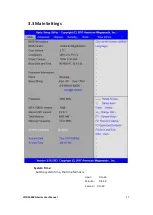
Page 55: ...Screen After CMOS discharge or BIOS flashing operation press Delete key to enter CMOS Setup After optimizing and exiting CMOS Setup 3 2 BIOS Setup Utility Press Delete key to enter BIOS Setup utility during POST and then a main menu containing system summary information will appear ...

Page 56: ...VITAM 9XXA Series User Manual 55 3 3 Main Settings System Time Set the system time the time format is Hour 0 to 23 Minute 0 to 59 Second 0 to 59 ...

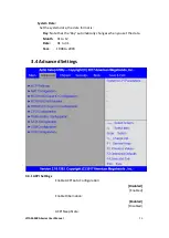
Page 57: ...date format is Day Note that the Day automatically changes when you set the date Month 01 to 12 Date 01 to 31 Year 1998 to 2099 3 4 Advanced Settings 3 4 1 ACPI Settings Enable ACPI Auto Configuration Disabled Enabled Enable Hibernation Enabled Disabled ACPI Sleep State ...

Page 58: ...led MEBx Selection Screen Disabled Hide Un Configure ME Configuration Disabled Prompt MEBx Debug Message Output Disabled Un Configure ME Disabled Amt Wait Timer 0 ASF Enabled Activate Remote Assistance Process Disabled USB Provisioning of AMT Enabled PET Progress Enabled AMT CIRA Timeout 0 WatchDog Disabled OS Timer 0 BIOS Timer 0 3 4 3 NCT6106D Super IO Configuration Super IO Chip NCT6106D Serial...

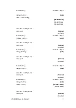
Page 59: ...e Settings Auto Serial Port 3 Configuration Serial port Enabled Disabled Device Settings IO 3E8h IRQ 7 Change Settings Auto Serial Port 4 Configuration Serial port Enabled Disabled Device Settings IO 2E8h IRQ 7 Change Settings Auto Serial Port 5 Configuration Serial port Enabled Disabled Device Settings IO 2F0h IRQ 7 Change Settings Auto COM5 Config RS 485 Mode RS 422 Mode Serial Port 6 Configurat...

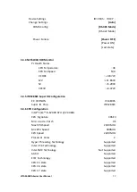
Page 60: ...3V 3 472V 3 4 5 IT8528SEC Super IO Configuration EC VERSION 7114E005 Super IO Chip IT8528SEC 3 4 6 CPU Configuration Intel Core i5 6200U CPU 2 30GHz CPU Signature 406E3 Microcode Patch 9E Max CPU Speed 2300 MHz Mix CPU Speed 400MHz CPU Speed 2200 MHz Processor Cores 2 Hyper Threading Technology Supported Intel VT X Technology Supported Intel SMX Technology Not Supported 64 bit Supported EIST Techn...

Page 61: ...ax Non Turbo Performance Intel R Speed Shift Technology Enabled Intel R SpeedStep tm Enabled Turbo Mode Enabled Package Power Limit MSR Lock Disabled 1 Core Ratio Limit Override 0 2 Core Ratio Limit Override 0 Configurable TDP Boot Mode Nominal Configurable TDP Lock Disabled CTDP BIOS control Disabled Platform PL1 Enable Disabled Platform PL2 Enable Disabled CPU C states Enabled Enhanced C states ...

Page 62: ...ensions SGX Software Controlled Select Owner EPOCH input type No Change In Owner EPOCHS PRMRR Size AUTO 3 4 7 Platform Misc Configuration Native PCIE Enable Enabled Native ASPM Auto BDAT ACPI Table Support Disabled Intel Ready Mode Technology Disabled ACPI Debug Disabled PTID Support Enabled PECI Access Method Direct I O Firmware Configuration Test ZpODD Support Disabled PCI Delay Optimization Dis...

Page 63: ...abled SATA Mode AHCI SATA Test Mode Disabled Software Feature Mask SATA Controller Aggressive LPM Support Enabled SATA Controller Speed Default Serial ATA Port 0 Empty Software Preserve Unknown Port 0 Enabled Hot Plug Disabled External SATA Disabled Spin Up Device Disabled SATA Device Type Hard Disk Drive Topology Unknown Device Sleep Disabled SATA DEVSLEP Idle Timeout Config Disabled Serial ATA P...

Page 64: ...Timeout Config Disabled Serial ATA Port 3 Empty Software Preserve Unknown Port 3 Enabled Hot Plug Disabled External SATA Disabled Spin Up Device Disabled SATA Device Type Hard Disk Drive Topology Unknown Device Sleep Disabled SATA DEVSLEP Idle Timeout Config Disabled Serial ATA Port 4 Empty Software Preserve Unknown Port 4 Enabled Hot Plug Disabled External SATA Disabled Spin Up Device Disabled SA...

Page 65: ...fig Disabled 3 4 9 CSM Configuration Compatibility Support Module Configuration CSM Support Enabled CSM16 Module Version 07 79 GateA20 Active Upon Request Option ROM Messages Force BIOS INT19 Trap Response Immediate Boot option filter UEFI and Legacy Option ROM execution Network Do not launch Storage UEFI Video Legacy Other PCI devices UEFI 3 4 10 USB Configuration USB Module Version 16 USB Contro...

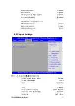
Page 66: ...rdware delays and time outs USB transfer time out 20 sec Device reset time out 20 sec Device power up delay Auto 3 5 Chipset Settings 3 5 1 System Agent SA Configuration System Agent Bridge Name Skylake SA PCIe Code Version 2 0 0 0 VT d Supported VT d Enabled Primary IGFX Boot Display VBIOS Deafault Secondary IGFX Boot Display Disabled Active LFP eDP Port A ...

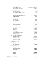
Page 67: ...8MB Aperture Size 256MB DVMT Pre Allocated 32M DVMT Total Gfx Mem 256M Gfx Low Power Mode Enabled VDD Enable Enabled PM Support Enabled PAVP Enable Enabled Cdynmax Clamping Enable Enabled Cd Clock Frequency 675MHz Intel Ultrabook Event Support IUER Slate Enable Disabled IUER Dock Enable Disabled IUER Button Enable Disabled DMI OPI Configuration DMI Vc1 Control Disabled DMI Vcm Control Enabled Memo...

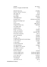
Page 68: ... Retrain on Fast fall Enabled Enable RH Prevention Enabled Row Hammer Solution Hardware RHP RH Activation Probability 1 2 11 Exit On Failure MRC Enabled MC Lock Enabled Probeless Trace Disabled Enable Disable IED Intel Enhanced Debug Disabled Ch Hash Support Enabled Ch Hash Mask 12488 Ch Hash Interleaved Bit BIT8 VC1 Read Metering Enabled VC1 RdMeter Time Window 800 VC1 RdMeter Threshold 280 Stron...

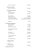
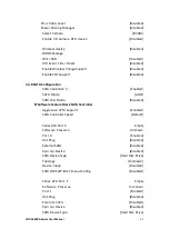
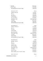
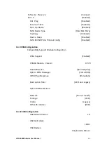
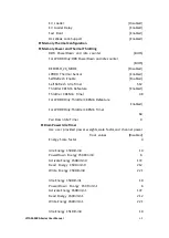
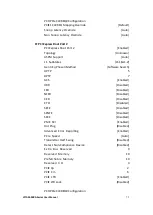
Page 69: ...ottler CKEMin Defeature Enabled Throttler CKEMin Timer 48 For LPDDR Only Throttler CKEMin Defeature Enabled For LPDDR Only Throttler CKEMin Timer 64 Pwr Down Idle Timer 0 Dram Power Idle Timer Use user provided power weights scale factor and channel power floor values Disabled Energy Scale factor 4 Idle Energy Ch0Dimm0 10 PowerDown Energy Ch0Dimm0 6 Activate Energy Ch0Dimm0 172 Read Energy Ch0Dimm...

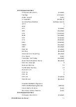
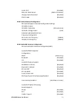
Page 70: ...gy Ch1Dimm1 172 Read Energy Ch1Dimm1 212 Write Energy Ch1Dimm1 221 Memory Thermal Reporting Lock Thermal Management Registers Enabled Memory Thermal Reporting Extern Therm Status Disabled Closed Loop Therm Manage Disabled Open Loop Therm Manage Disabled Thermal Threhold Settings Warm Threshold Ch0 Dimm0 255 Warm Threshold Ch0 Dimm1 255 Hot Threshold Ch0 Dimm0 255 Hot Threshold Ch0 Dimm1 255 Warm T...

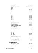
Page 71: ...WindowX 0 RAPL PL 1 WindowY 0 RAPL PL 1 enable Disabled RAPL PL 1 Power 0 RAPL PL 1 WindowX 0 RAPL PL 1 WindowY 0 Memory Thermal Management Disabled Memory Training Algorithms Early Command Training Disabled SenseAmp Offset Training Enabled Early ReadMPR Timing Centering 2D Enabled Read MPR Training Enabled Receive Enable Training Enabled Jedec Write Leveling Enabled Early Write Time Centering 2D ...

Page 72: ...ge Centering 2D Enabled Late Command Training Enabled Round Trip Latency Enabled Turn Around Timing Training Enabled Rank Margin Tool Disabled Memory Test Disabled DIMM SPD Alias Test Enabled Receive Enable Centering 1D Enabled Retrain Margin Check Enabled Command Power Training Disabled GT Power Management Control GT Info GT2 RC6 Render Standby Enabled 3 5 2 PCH IO Configuration Intel PCH RC Vers...

Page 73: ...ort Auto L1 SubStates L1 1 L1 2 Gen3 Eq Phase3 Method Software Search UPTP 5 DPTP 7 ACS Enabled URR Disabled FER Disabled NFER Disabled CER Disabled CTO Disabled SEFE Disabled SENFE Disabled SECE Disabled PME SCI Enabled Hot Plug Disabled Advanced Error Reporting Enabled PCIe Speed Auto Transmitter Half Swing Disabled Detect Non Compliance Device Disabled Extra Bus Reserved 0 Reserved Memory 10 Pr...

Page 74: ...Phase3 Method Software Search UPTP 5 DPTP 7 ACS Enabled URR Disabled FER Disabled NFER Disabled CER Disabled CTO Disabled SEFE Disabled SENFE Disabled SECE Disabled PME SCI Enabled Hot Plug Disabled Advanced Error Reporting Enabled PCIe Speed Auto Transmitter Half Swing Disabled Detect Non Compliance Device Disabled Extra Bus Reserved 0 Reserved Memory 10 Prefetchable Memory 10 Reserved I O 4 PCIE...

Page 75: ...Enabled URR Disabled FER Disabled NFER Disabled CER Disabled CTO Disabled SEFE Disabled SENFE Disabled SECE Disabled PME SCI Enabled Hot Plug Disabled Advanced Error Reporting Enabled PCIe Speed Auto Transmitter Half Swing Disabled Detect Non Compliance Device Disabled Extra Bus Reserved 0 Reserved Memory 10 Prefetchable Memory 10 Reserved I O 4 PCIE Cp 2 PCIE Cm 6 PCIE LTR Enabled PCIE LTR Lock D...

Page 76: ...ER Disabled CTO Disabled SEFE Disabled SENFE Disabled SECE Disabled PME SCI Enabled Hot Plug Disabled Advanced Error Reporting Enabled PCIe Speed Auto Transmitter Half Swing Disabled Detect Non Compliance Device Disabled Extra Bus Reserved 0 Reserved Memory 10 Prefetchable Memory 10 Reserved I O 4 PCIE Cp 2 PCIE Cm 6 PCIE LTR Enabled PCIE LTR Lock Disabled PCH PCIe CLKREQ Configuration PCIE4 CLKRE...

Page 77: ... Disabled SECE Disabled PME SCI Enabled Hot Plug Disabled Advanced Error Reporting Enabled PCIe Speed Auto Transmitter Half Swing Disabled Detect Non Compliance Device Disabled Extra Bus Reserved 0 Reserved Memory 10 Prefetchable Memory 10 Reserved I O 4 PCIE Cp 2 PCIE Cm 6 PCIE LTR Enabled PCIE LTR Lock Disabled PCH PCIe CLKREQ Configuration PCIE5 CLKREQ Mapping Override Default Snoop Latency Oce...

Page 78: ...ed Hot Plug Disabled Advanced Error Reporting Enabled PCIe Speed Auto Transmitter Half Swing Disabled Detect Non Compliance Device Disabled Extra Bus Reserved 0 Reserved Memory 10 Prefetchable Memory 10 Reserved I O 4 PCIE Cp 2 PCIE Cm 6 PCIE LTR Enabled PCIE LTR Lock Disabled PCH PCIe CLKREQ Configuration PCIE6 CLKREQ Mapping Override Default Snoop Latency Ocerride Auto Non Snoop Latency Ocerride...

Page 79: ...led Advanced Error Reporting Enabled PCIe Speed Auto Transmitter Half Swing Disabled Detect Non Compliance Device Disabled Extra Bus Reserved 0 Reserved Memory 10 Prefetchable Memory 10 Reserved I O 4 PCIE Cp 2 PCIE Cm 6 PCIE LTR Enabled PCIE LTR Lock Disabled PCH PCIe CLKREQ Configuration PCIE7 CLKREQ Mapping Override Default Snoop Latency Ocerride Auto Non Snoop Latency Ocerride Auto PCI Express...

Page 80: ...porting Enabled PCIe Speed Auto Transmitter Half Swing Disabled Detect Non Compliance Device Disabled Extra Bus Reserved 0 Reserved Memory 10 Prefetchable Memory 10 Reserved I O 4 PCIE Cp 2 PCIE Cm 6 PCIE LTR Enabled PCIE LTR Lock Disabled PCH PCIe CLKREQ Configuration PCIE8 CLKREQ Mapping Override Default Snoop Latency Ocerride Auto Non Snoop Latency Ocerride Auto PCI Express Root Port 9 PCI Expr...

Page 81: ...nsmitter Half Swing Disabled Detect Non Compliance Device Disabled Extra Bus Reserved 0 Reserved Memory 10 Prefetchable Memory 10 Reserved I O 4 PCIE Cp 2 PCIE Cm 6 PCIE LTR Enabled PCIE LTR Lock Disabled PCH PCIe CLKREQ Configuration PCIE9 CLKREQ Mapping Override Default Snoop Latency Ocerride Auto Non Snoop Latency Ocerride Auto PCI Express Root Port 10 PCI Express Root Port 10 Enabled Topology ...

Page 82: ...ed Detect Non Compliance Device Disabled Extra Bus Reserved 0 Reserved Memory 10 Prefetchable Memory 10 Reserved I O 4 PCIE Cp 2 PCIE Cm 6 PCIE LTR Enabled PCIE LTR Lock Disabled PCH PCIe CLKREQ Configuration PCIE10 CLKREQ Mapping Override Default Snoop Latency Ocerride Auto Non Snoop Latency Ocerride Auto PCI Express Root Port 11 PCI Express Root Port 11 Enabled Topology Unknown ASPM Support Auto...

Page 83: ...Non Compliance Device Disabled Extra Bus Reserved 0 Reserved Memory 10 Prefetchable Memory 10 Reserved I O 4 PCIE Cp 2 PCIE Cm 6 PCIE LTR Enabled PCIE LTR Lock Disabled PCH PCIe CLKREQ Configuration PCIE11 CLKREQ Mapping Override Default Snoop Latency Ocerride Auto Non Snoop Latency Ocerride Auto PCI Express Root Port 12 PCI Express Root Port 12 Enabled Topology Unknown ASPM Support Auto L1 SubSta...

Page 84: ...a Bus Reserved 0 Reserved Memory 10 Prefetchable Memory 10 Reserved I O 4 PCIE Cp 2 PCIE Cm 6 PCIE LTR Enabled PCIE LTR Lock Disabled PCH PCIe CLKREQ Configuration PCIE12 CLKREQ Mapping Override Default Snoop Latency Ocerride Auto Non Snoop Latency Ocerride Auto USB Configuration USB Precondition Disabled XHCI Disable Compliance Mode FALSE xDCI Support Disabled USB Port Disable Override Disabled B...

Page 85: ...D Audio Link Frequency 24MHz iDisplay Link Frequency 96MHz HD Audio DSP Features Configuration HD Audio Subsystem Features Configuration ACPI Audio DSP NHLT Endpoints Configuration DMIC 4 Mic Array Bluetooth Disabled I2S Disabled Audio DSP Feature Support WoV Wake on Voice Disabled Bluetooth Sideband Disabled BT Intel HFP Disabled BT Intel A2DP Disabled Codec based VAD Disabled DSP based Speech Pr...

Page 86: ...Disabled I2C1 Controller Disabled I2C2 Controller Disabled I2C3 Controller Disabled I2C4 Controller Disabled I2C5 Controller Disabled SPI0 Controller Disabled SPI1 Controller Disabled UART0 Controller Disabled UART1 Controller Disabled UART2 Controller Disabled GPIO Controller Enabled Serial IO GPIO Settings GPIO IRQ Route IRQ14 WITT MITT Test Device Disabled UART Test Device Disabled Addtional Se...

Page 87: ...bled PORT C D CTLE Enabled PORT A CTLE CAP Value e PORT A CTLE RES Value d PORT B CTLE CAP Value e PORT B CTLE RES Value d PORT C D CTLE CAP Value e PORT C D CTLE RES Value d PORT A TRIM Enabled PORT B TRIM Enabled PORT C TRIM Enabled PORT D TRIM Enabled PORT A Data Trim Value bbbb PORT B Data Trim Value bbbb PORT C D Data Trim Value cccc PORT A Clk Trim Value a PORT B Clk Trim Value a PORT C Clk ...

Page 88: ...AID ROM Legacy ROM DCI enable HDCIEN Disabled DCI Auto Detect Enabled Enabled Debug Port Selection Legacy UART GNSS Disabled PCH LAN Controller Enabled LAN PHY Drives LAN_WAKE Disabled Sensor Hub Type None DeepSx Power Policies Disabled LAN Wake From DeepSx Enabled Wake on LAN Enabled SLP_LAN Low on DC Power Enabled K1 off Enabled Wake on WLAN Enable Disabled Disable DSX ACPRESENT PullDown Disable...

Page 89: ...88 Compatible Revision ID Disabled PCH Cross Throttling Enabled Disable Energy Reporting Disabled Capsule Reset Type Capsule S3 Resume Pcie Pll SSC Auto IOAPIC 24 119 Entries Enabled Unlock PCH P2SB Disabled PMC READ DISABLE Enabled ...

Page 90: ...e password again and press Enter key You may press Esc key to abandon password entry operation To clear the password just press Enter key when password input window pops up A confirmation message will be shown on the screen as to whether the password will be disabled You will have direct access to BIOS setup without typing any password after system reboot once the password is disabled Once the pas...

Page 91: ...enter the password prior to system boot to control unauthorized access to your computer Users may enable the feature in Security Option of Advanced BIOS Features If Security Option is set to System you will be requested to enter the password before system boot and when entering BIOS setup if Security Option is set to Setup you will be requested for password for entering BIOS setup ...

Page 92: ...XXA Series User Manual 91 3 7 Boot Settings Setup Prompt Timeout 1 Bootup Numlock State On Quiet Boot Disabled Boot Option Priorities Fast Boot Disabled Driver Option Priorities New Boot Option Policy Default ...

Page 93: ...xit Save Exit Setup save Configuration and exit Yes No Discard Changes and Ext Exit Without Saving Quit without saving Yes No Save Changes and Reset Reset the system affer Saving The changes Yes No Discard Changes and Reset Reset system setup without Saving any changes Yes No ...

Page 94: ...ar to any of the setup options Yes No Restore Defaults Restore Load Defaults values for all the setup options Yes No Save as user Defaults Save the changes done so far as User Defaults Yes No Restore user Defaults Restore the User Defaults to all the setup options Yes No Boot Override Launch EFI Shell from filesystem device WARNING Not Found ok ...

Page 95: ...ivers are included with the motherboard The contents include Intel H170 Graphics 530 chipset driver Audio driver Intel management engine interface and DPTF Driver Installation instructions are given below Important Note After installing your Windows operating system you must install first the Intel Chipset Software Installation Utility before proceeding with the installation of drivers ...

Page 96: ...Intel H170 Chipset To install the Intel H170 chipset driver please follow the steps below Step 1 Select Intel H170 Chipset from the list Step 2 Here is welcome page Please make sure you save and exit all programs before install Click Next ...

Page 97: ...VITAM 9XXA Series User Manual 96 Step3 Read the license agreement Click Accept to accept all of the terms of the license agreement Step4 Click Install to begin the installation ...

Page 98: ...VITAM 9XXA Series User Manual 97 Step5 Select Restart Now to reboot your computer for the changes to take effect ...

Page 99: ...XXA Series User Manual 98 4 2 Intel HD Graphics 530 Chipset To install the Intel HD Graphics 530 Chipset please follow the steps below Step 1 Select Intel HD Graphics 530 Chipset from the list Step2 Click Next ...

Page 100: ...VITAM 9XXA Series User Manual 99 Step3 Choose automatically run function and Click Next to setup program Step4 Read the license agreement Click Yes to accept all of the terms of the license agreement ...

Page 101: ...AM 9XXA Series User Manual 100 Step5 Click Next to continue Step6 Here is Intel product improvement program information you can choose Accept or Decline by your option and installation will go to next step ...

Page 102: ...VITAM 9XXA Series User Manual 101 Step7 Click Next to continue the program Step8 Select Yes I want to restart this computer now Click Finish to complete installation ...

Page 103: ...r Manual 102 4 3 Realtek ALC662 HD Audio Driver Installation To install the Realtek ALC662 HD Audio Driver please follow the steps below Step1 Select Realtek AL662 HD Audio Driver from the list Step2 Click Next to continue ...

Page 104: ...VITAM 9XXA Series User Manual 103 Step3 Click Yes I want to restart my computer now Click Finish to complete the installation ...

Page 105: ...install the Intel Management Engine Interface please follow the steps below Step1 Select Intel Management Engine Interface from the list Step2 Select setup language you need Click Next to continue Step3 Choose I accept the terms in the License Agreement and click Next to begin ...

Page 106: ...VITAM 9XXA Series User Manual 105 the installation Step4 Click Next to continue ...

Page 107: ...VITAM 9XXA Series User Manual 106 Step5 Click Finish to complete the installation ...

Page 108: ...VITAM 9XXA Series User Manual 107 4 5 DPTF Driver To install the DPTF Driver please follow the steps below Step1 Select DPTF Driver from the list Step2 Click Next to continue ...

Page 109: ...Series User Manual 108 Step3 Read the license agreement Choose Accept and click Next to accept all of the terms of the license agreement Step4 Select destination location by your option and click Next to continue ...

Page 110: ...VITAM 9XXA Series User Manual 109 Step5 Click Install to continue the installing Step6 Click Finish to complete the installation and start install Intel DPTF driver for Windows ...

Page 111: ...VITAM 9XXA Series User Manual 110 Step7 Click Next to start the installation Step8 Read the license agreement Click Yes to accept all of the terms of the license agreement Step9 Click Next to continue ...

Page 112: ...VITAM 9XXA Series User Manual 111 Step10 Click Finish to complete the installation ...

Page 113: ... 8 1 10 driver software you must have the Windows 8 1 10 system installed and running on your computer You must also have one of the following PenMount 6000 series controller or control boards installed PM6500 PM6300 Resistive Touch If you have an older version of the PenMount Windows 7 driver installed in your system please remove it first Follow the steps below to install the PenMount DMC6000 Wi...

Page 114: ...VITAM 9XXA Series User Manual 113 Step2 Click Next to continue Step3 Read the license agreement Click I Agree to agree the license agreement ...

Page 115: ...VITAM 9XXA Series User Manual 114 Step4 Choose the folder in which to install PenMount Windows Universal Driver Click Install to start the installation Step5 Click Yes to continue ...

Page 116: ...VITAM 9XXA Series User Manual 115 Step6 Click Finish to complete installation ...

Page 117: ...to carry out calibration 1 After installation click the PenMount Monitor icon PM in the menu bar 2 When the PenMount Control Panel appears select a device to Calibrate PenMount Control Panel Resistive Touch The functions of the PenMount Control Panel are Device Multiple Monitors Tools and About which are explained in the following sections Device In this window you can find out that how many devic...

Page 118: ...ting to red squares Use your finger or stylus to touch the red squares in sequence After the fifth red point calibration is complete To skip press ESC Advanced Calibration Advanced Calibration uses 4 9 16 or 25 points to effectively calibrate touch panel linearity of aged touch screens Click this button and touch the red squares in sequence with a stylus To skip press ESC Step1 Please select a dev...

Page 119: ...dard Calibration to start calibration procedure NOTE The older the touch screen the more Advanced Mode calibration points you need for an accurate calibration Use a stylus during Advanced Calibration for greater accuracy Please follow the step as below ...

Page 120: ...or greater accuracy Plot Calibration Data Check this function and a touch panel linearity comparison graph appears when you have finished Advanced Calibration The blue lines show linearity before calibration and black lines show linearity after calibration Turn off EEPROM storage The function disable for calibration data to write in Controller The default setting is Enable ...

Page 121: ...use only provides a click function and dragging is disables Beep Sound Enable Beep Sound turns beep function on and off Beep on Pen Down beep occurs when pen comes down Beep on Pen Up beep occurs when pen is lifted up Beep on both beep occurs when comes down and lifted up Beep Frequency modifies sound frequency Beep Duration modifies sound duration Cursor Stabilizer Enable the function support to ...

Page 122: ...VITAM 9XXA Series User Manual 121 Edge Compensation You can use Edge Compensation to calibrate more subtly About This panel displays information about the PenMount controller and driver version ...

Page 123: ...for a single monitor Multiple Monitors support the following modes Windows Extends Monitor Function Matrox DualHead Multi Screen Function nVidia nView Function NOTE The Multiple Monitor function is for use with multiple displays only Do not use this function if you have only one touch screen display Please note once you turn on this function the rotating function is disabled Enable the multiple di...

Page 124: ...pear Touch the red squares in sequence 8 Continue calibration for each monitor by clicking Standard Calibration and touching the red squares NOTES 1 If you use a single VGA output for multiple monitors please do not use the Multiple Monitor function Just follow the regular procedure for calibration on each of your desktop monitors 2 The Rotating function is disabled if you use the Multiple Monitor...

Page 125: ...Windows 7 8 8 1 system when you turn on PenMount Monitor in PenMount Utilities PenMount Monitor has the following function Control Panel Open Control Panel Windows Beep Setting Beep function for each device Right Button When you select this function a mouse icon appears in the right bottom of the screen Click this icon to switch between Right and Left Button functions Exit Exits the PenMount Monit...

Page 126: ...ction 1 Install the rotation software package 2 Choose the rotate function 0 90 180 270 in the 3rd party software The calibration screen appears automatically Touch this point and rotation is mapped NOTE The Rotate function is disabled if you use Monitor Mapping ...

Reviews: